
Clamping mechanism of cylindrical workpieces

A clamping mechanism, cylindrical technology, applied in the direction of metal processing machinery parts, clamping, manufacturing tools, etc., can solve the problems of poor applicability, uncontrollable clamping force, etc., and achieve the effect of wide application range

Inactive Publication Date: 2015-04-08
CHONGQING ANTAI SPRING IND
View PDF0 Cites 24 Cited by
  • Summary
  • Abstract
  • Description
  • Claims
  • Application Information

AI Technical Summary

Problems solved by technology

[0005] The technical problem to be solved by the present invention is to provide a clamping force that can be adjusted according to the diameter of the workpiece and has strong applicability in view of the shortcomings of the existing expansion sleeve clamping device for cylindrical workpieces that cannot control the clamping force and poor applicability. Clamping mechanism for cylindrical workpieces

Method used


Image

  • Clamping mechanism of cylindrical workpieces

Examples


Embodiment Construction

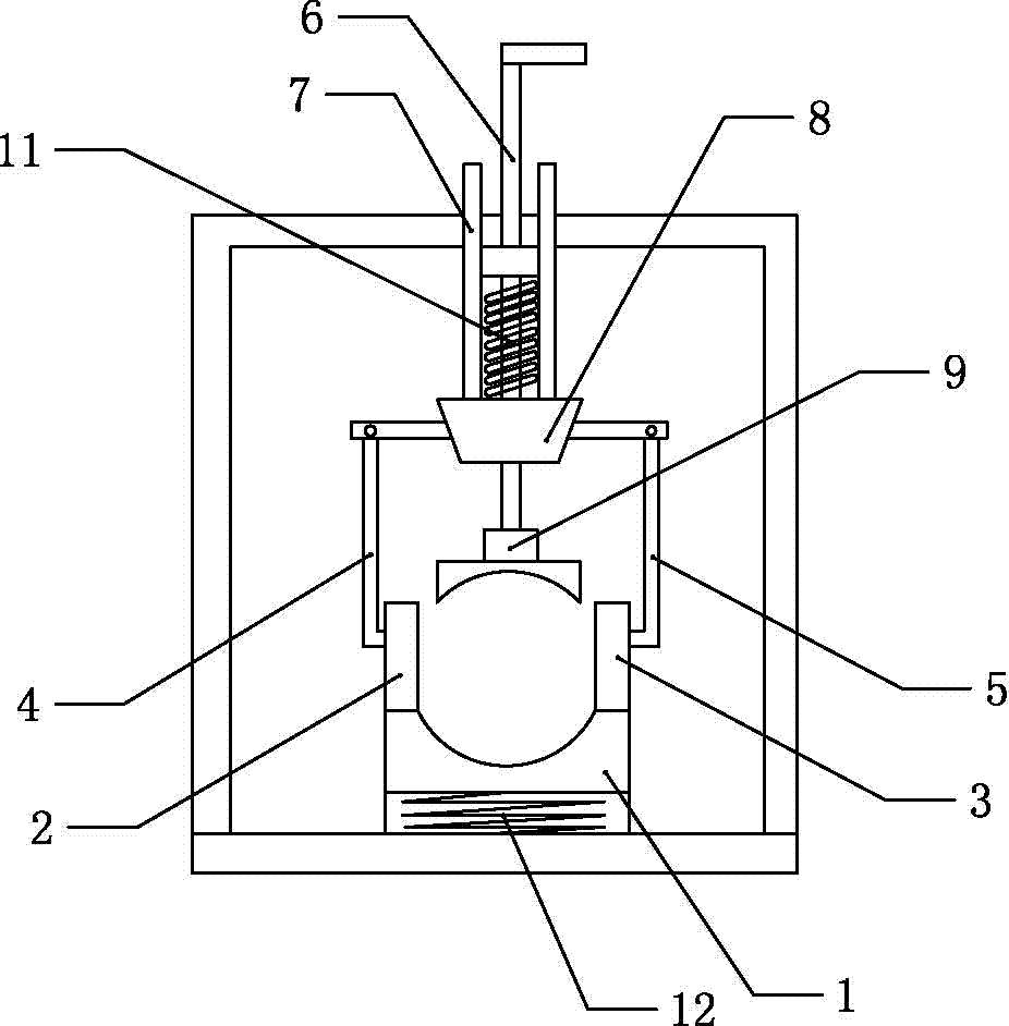
[0014] In the figure: lower splint 1, left splint 2, right splint 3, left chuck 4, right chuck 5, sliding rod 6, pull rod 7, tapered slider 8, top pressure block 9, first spring 10, second spring 11.

[0015] Such as figure 1 As shown, the clamping mechanism of the cylindrical workpiece of the present invention comprises a base, an upper clamping plate and a lower clamping plate 1, the lower clamping plate 1 is fixed on the base, a second spring 11 is arranged between the lower clamping plate 1 and the base, and the base There is a shell on the top, and the upper bolt of the lower splint 1 is connected with a lower groove plate with an arc-shaped groove on the upper end; the upper splint includes a pressing device and a left splint 2 and a right splint 3 with arc-shaped grooves on the inner side , the pressing device includes a left jaw, a right jaw, a slide bar 6, a tapered slide block 8 and a top pressure block 9, the lower end of the top pressure block 9 has an arc groove,...


PUM


Abstract

The invention discloses a clamping mechanism of cylindrical workpieces. The clamping mechanism comprises a base, an upper clamping plate and a lower clamping plate. The lower clamping plate is fixed on the base. The upper clamping plate comprises a top pressure device, a left clamping plate and a right clamping plate, and the left clamping plate and the right clamping plate are provided with arc grooves respectively. The top pressure device comprises a left clamping jaw, a right clamping jaw, a sliding rod, a conical sliding block and a top pressure block. An arc groove is formed in the lower end of the top pressure block, a support is arranged on the base and connected with the sliding rod, and the lower end of the sliding rod penetrates through the conical sliding block to be vertically connected with the upper end of the top pressure block. The small-diameter end of the conical sliding block is close to the top pressure block, and the big-diameter end of the conical sliding block is far away from the top pressure block. A pull rod is arranged at the upper end of the conical sliding block, and the lower portion of the left clamping jaw butts against the outer wall of the left clamping plate. The lower portion of the right clamping jaw butts against the outer wall of the right clamping plate. The clamping mechanism of cylindrical workpieces overcomes defects of the existing expanding sleeve type clamping device of the cylindrical workpieces of incapability in clamping force control and poor applicability; can adjust the clamping strength according to the diameters of the workpieces, and is strong in applicability.

Description

technical field [0001] The invention belongs to the field of clamping devices, in particular to a clamping mechanism for cylindrical workpieces. Background technique [0002] Spring is a mechanical part that uses elasticity to work. Parts made of elastic materials are deformed under the action of external force and return to their original shape after removing the external force. They are generally made of spring steel. The types of springs are complex and diverse. According to the shape, there are mainly coil springs, scroll springs, leaf springs, special-shaped springs, etc. [0003] According to the nature of the force, the spring can be divided into tension spring, compression spring, torsion spring and bending spring, and can be divided into disc spring, ring spring, plate spring, coil spring, truncated cone scroll spring and torsion bar spring according to the shape. According to the production process, it can be divided into cold coil spring and hot coil spring. [...

Claims


Application Information

Patent Timeline
Patent Type & Authority Applications(China)
IPC IPC(8): B23Q3/06
CPCB23Q3/062
Inventor 袁文敏
Owner CHONGQING ANTAI SPRING IND
Learn More