Gas valve with working state indicating function

A technology of working state indication and gas valve, which is applied to valve devices, point light sources, components of lighting devices, etc., can solve the problems of high cost and complex structure, and achieve the effect of enhancing appreciation

Active Publication Date: 2015-04-08
NINGBO CHAOYANG HOUSEHOLD GAS STOVES
View PDF5 Cites 17 Cited by
  • Summary
  • Abstract
  • Description
  • Claims
  • Application Information

AI Technical Summary

Problems solved by technology

[0006] The existing safety indication structure needs to be set up...

Method used


Image

  • Gas valve with working state indicating function
  • Gas valve with working state indicating function
  • Gas valve with working state indicating function

Examples


Embodiment Construction

[0025] The present invention will be further described in detail below in conjunction with the accompanying drawings and embodiments.

[0026] Such as Figure 1~6 Shown is a preferred embodiment of the present invention.

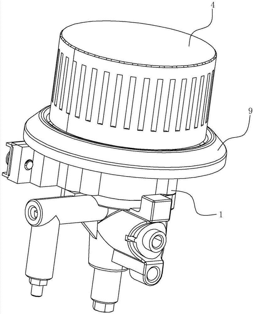
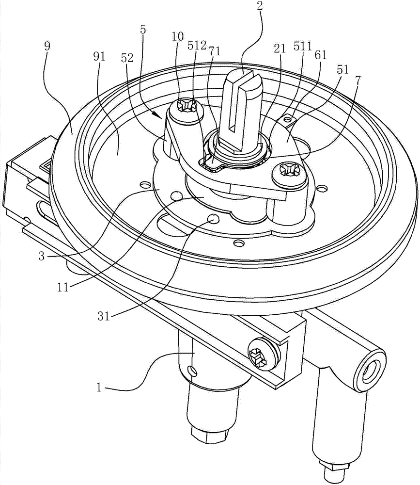
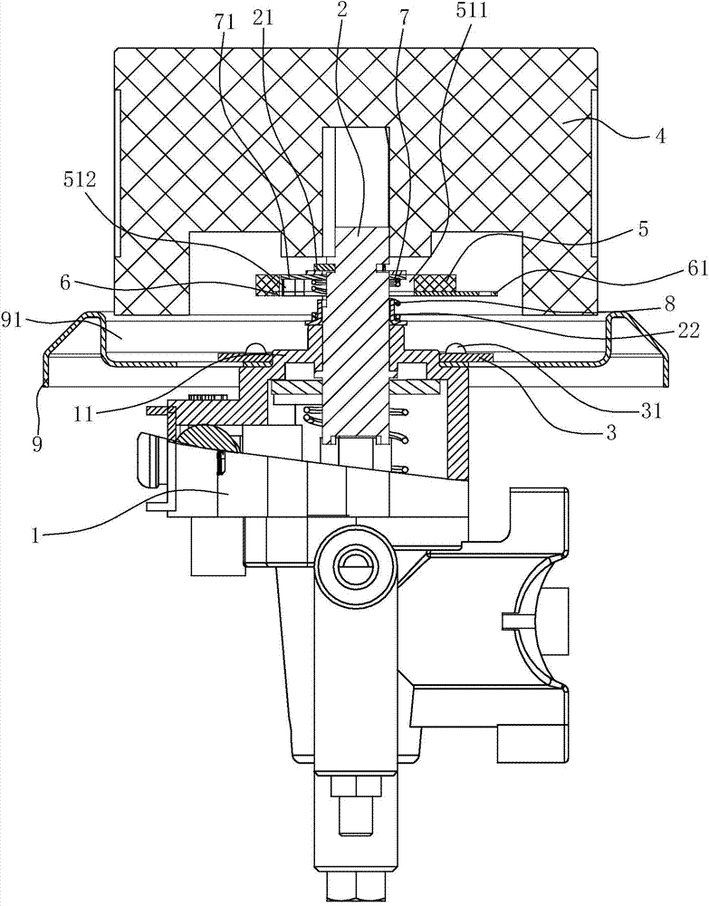
[0027] A gas valve with a working state indication function, comprising a valve body 1 and a valve stem 2 pierced on the valve body 1 , and a knob 4 for driving the valve stem 2 to rotate is installed on the valve stem 2 . As a complete gas valve, the valve body is equipped with a valve core and a supporting spring acting on the valve stem. The specific structure inside the gas valve can refer to various existing gas valves.

[0028] A circuit board 3 with an LED light 31 and a bracket 5 made of non-conductive material are fixed on the valve body 1. One pole of the circuit board 3 is connected to the valve body 1. The circuit board 3 is in a ring shape, and the valve stem 2 passes through The central hole of the circuit board 3 and the other pole of the c...


PUM


Abstract

The invention relates to a gas valve with the working state indicting function. The gas valve comprises a valve body, and a valve rod which passes through the valve body; a knob is mounted on the valve rod. The gas valve is characterized in that a circuit board with an LED lamp and a bracket prepared from a nonconductive material are fixed on the valve body; a metal conductive ring is fixed on the lower end surface of the bracket; a conductive sheet which can rotate together with the valve rod sleeves the valve rod; a lug which laterally protrudes is arranged at the side part of the conductive sheet; a through hole through which the conductive sheet passes is formed in the bracket; an opening through which the lug passes is formed in the circumferential wall of the through hole; the lug is aligned to the opening when the valve rod is in the primary state; the lug is staggered to the opening in the whole working state of the valve from downward pressing to deflect; the lug is located below the lower end surface of the bracket and is in conduction contact with the metal conductive ring all the time. According to the gas valve with the working state indicating function, the conductive sheet and the metal conductive ring are in contact or disconnected to control the LED lamp to be on or off; when in use after ignition of the gas valve, an indicator light is on all the time to remind of that a gas appliance is in a working state.

Description

technical field [0001] The invention relates to a gas valve used on a gas appliance, in particular to a gas valve with the function of indicating the working state. Background technique [0002] The gas valve used for gas appliances generally includes a valve body with an inlet channel and an outlet channel, a valve core with a large fire hole and a small fire hole in the valve body, and a valve stem. The valve stem has a spring top in the valve body. maintain an upward trend. The top of the valve stem will be connected with the knob installed on the cooker panel. When in use, the knob can be operated to control the knob rod. Generally, the knob should be pressed first and turned counterclockwise to drive the valve core to rotate counterclockwise to make the fire on the valve core The hole communicates with the air intake channel in the valve body. At this time, the gas source can be sprayed out from the nozzle through the air intake channel and the air outlet channel for u...

Claims


Application Information

Patent Timeline
IPC IPC(8): F16K37/00F21V33/00F21Y101/02
CPCF16K37/00F21V33/00
Inventor 李雪亚
Owner NINGBO CHAOYANG HOUSEHOLD GAS STOVES
Why Eureka
Try Eureka