Low-temperature adsorbent device for cryogenic pressure vessel and its production process

A pressure vessel and adsorbent technology, applied in the field of low-temperature adsorbent devices, can solve the problems that the flow area has not been effectively improved, the adsorption effect is difficult to play normally, and the penetration area of ​​the spherical sieve plate is small, so as to meet the functional requirements, Effect of reducing cracks and avoiding leakage

Active Publication Date: 2016-09-21
CRRC YANGTZE CO LTD
View PDF7 Cites 0 Cited by
  • Summary
  • Abstract
  • Description
  • Claims
  • Application Information

AI Technical Summary

Problems solved by technology

Once this happens, the container will lose its thermal insulation state, seriously affecting the safety of the container;
[0006] 2) The inner diameter of the central cylinder structure is small (130mm) and the length is long (2000mm). Due to the slender structure, the low-temperature adsorbent at the bottom is far away from the vacuum chamber, and the adsorption flow area is small, which makes it difficult to perform the adsorption effect normally. ;
[0007] 3) Although the cross-sectional size of the hat-shaped structure is larger than that of the central cylinder structure, the actual flow area has not been effectively improved compared with the central cylinder structure due to the small permeable area of ​​the spherical sieve plate , the adsorption effect is still not functioning normally

Method used


Image

  • Low-temperature adsorbent device for cryogenic pressure vessel and its production process
  • Low-temperature adsorbent device for cryogenic pressure vessel and its production process
  • Low-temperature adsorbent device for cryogenic pressure vessel and its production process

Examples


Embodiment Construction

[0030] In order to better explain the present invention, the main content of the present invention is further clarified below in conjunction with specific examples, but the content of the present invention is not limited to the following examples.

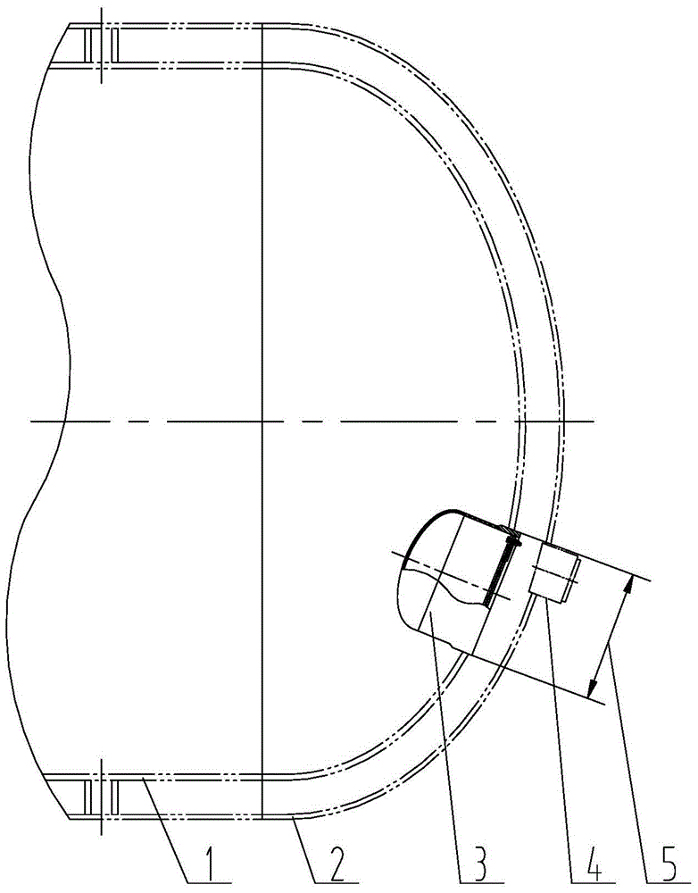
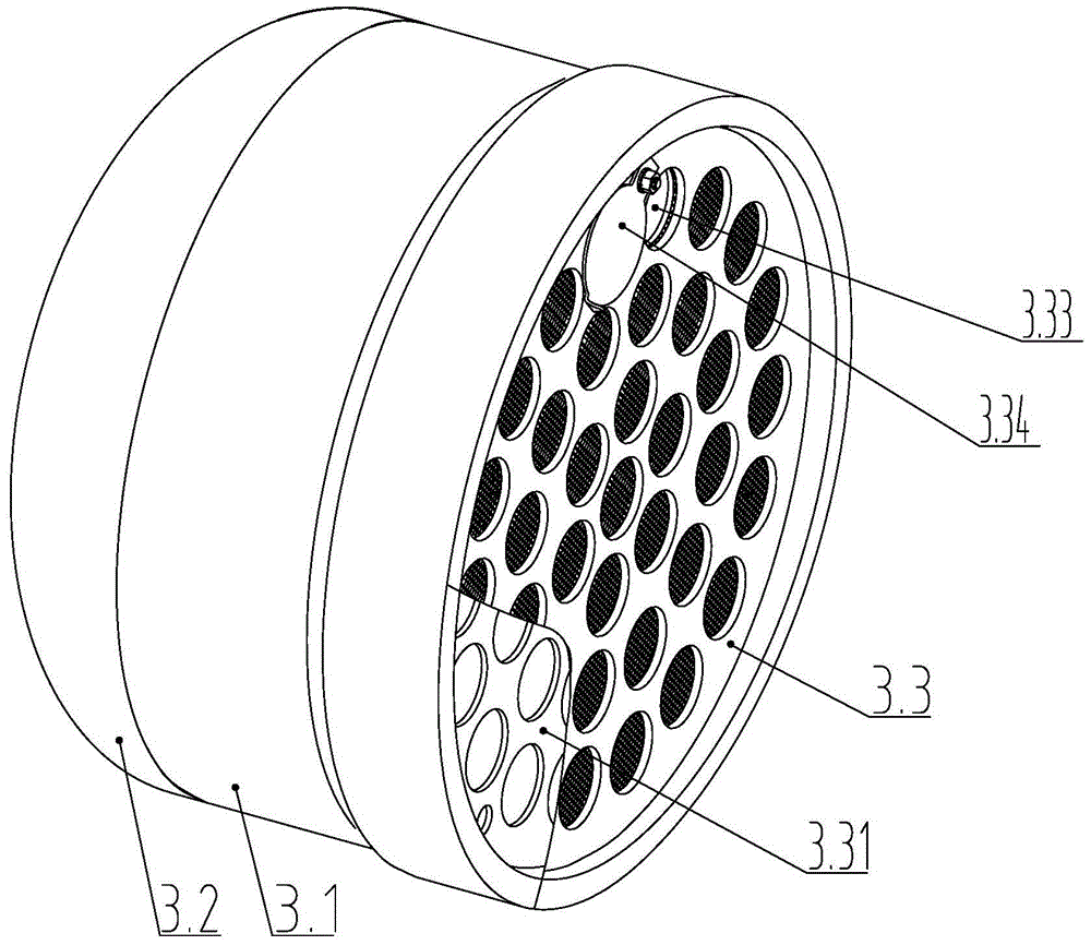
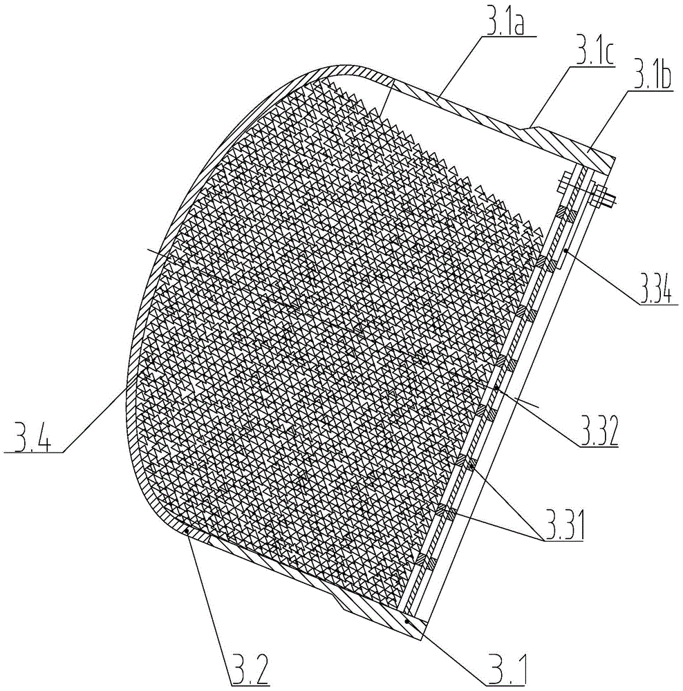
[0031] Such as Figure 1~3 The low-temperature adsorbent device used for cryogenic pressure vessel is shown, the cryogenic pressure vessel includes an inner vessel 1 and an outer vessel 2, and a process manhole 5 is opened on the middle and lower part of the head of the inner vessel 1, and the The head of the outer container 2 is provided with a feeding port 4 corresponding to the position of the process manhole 5. The low-temperature adsorbent device 3 is arranged on the process manhole 5. The low-temperature adsorbent device 3 includes an adsorbent cylinder 3.1, The adsorbent cylinder 3.1 has an upper cylinder section 3.1a and a lower cylinder section 3.1b with the same inner diameter but different outer diameters, and the cylind...


PUM


Abstract

The invention discloses a low-temperature adsorbing agent device for a cryogenic pressure container and a production process of the low-temperature adsorbing agent device. The cryogenic pressure container comprises an inner container and an outer container, wherein a process manhole is formed in the middle-lower part of an end enclosure of the inner container, a charging hole corresponding to the process manhole is formed in an end enclosure of the outer container, the low-temperature adsorbing agent device comprises an adsorbing agent cylinder body, wherein the adsorbing agent cylinder body is provided with an upper-part cylinder body section and a lower-part cylinder body section which are equal in inner diameters and different in outer diameters, an end enclosure of the cylinder body is smoothly welded at the open end part of the upper-part cylinder body section, a sieve plate device is welded at the inner side of the open end part of the lower-part cylinder body section, and the outer side of the open end part of the lower-part cylinder body section is welded on the process manhole. According to the low-temperature adsorbing agent device, by increasing the through-flow area, the efficiency of a low-temperature adsorbing agent is enhanced and improved; by improving the structure, the structure stress condition is improved, the hidden danger of the welding quality is eliminated, and the safety of the pressure container is improved; by improving the position arrangement, the operating condition is improved, and the labor intensity is lightened.

Description

technical field [0001] The invention relates to a low-temperature adsorbent device, in particular to a low-temperature adsorbent device for a cryogenic pressure vessel and a production process thereof. Background technique [0002] The vacuum degree of the insulation interlayer of the cryogenic pressure vessel is the key factor to ensure the insulation performance of the vacuum insulation cryogenic vessel. Setting the low-temperature adsorbent box in the vacuum interlayer is an important measure to maintain the vacuum in the interlayer. After vacuuming and sealing, the low-temperature adsorbent begins to absorb air leakage and outgassing of materials in the interlayer, which prolongs the life of the vacuum. How to make the low-temperature adsorbent fully exert its adsorption performance, the structural design and location arrangement of the low-temperature adsorbent device are particularly important. [0003] The cryogenic adsorbent devices currently in use include a centr...

Claims


Application Information

Patent Timeline
Patent Type & Authority Patents(China)
IPC IPC(8): F17C11/00F17C1/12F17C13/00
Inventor 李永莉王宝磊杨清义吕长乐
Owner CRRC YANGTZE CO LTD
Why Eureka
Try Eureka