Electronic power catapult booster

An electronic power and booster technology, applied in the direction of drying solid materials, lighting and heating equipment, drying, etc., to achieve the effect of stable objects

Active Publication Date: 2015-04-08
新昌县科博机械有限公司
View PDF3 Cites 1 Cited by
  • Summary
  • Abstract
  • Description
  • Claims
  • Application Information

AI Technical Summary

Problems solved by technology

[0002] The ejection booster uses the principle of electromagnet homosexual repulsion to start the engine A, and the low-speed gear drives the flywheel to fly. When the flywheel speed reaches a certain level, change to the medium-speed gear of A, and then change to the high-speed gear of A. After normal, The clutch B gear drives the rotating wheel to rotate, and the rotating wheel drives the teet

Method used


Image

  • Electronic power catapult booster

Examples


Embodiment Construction

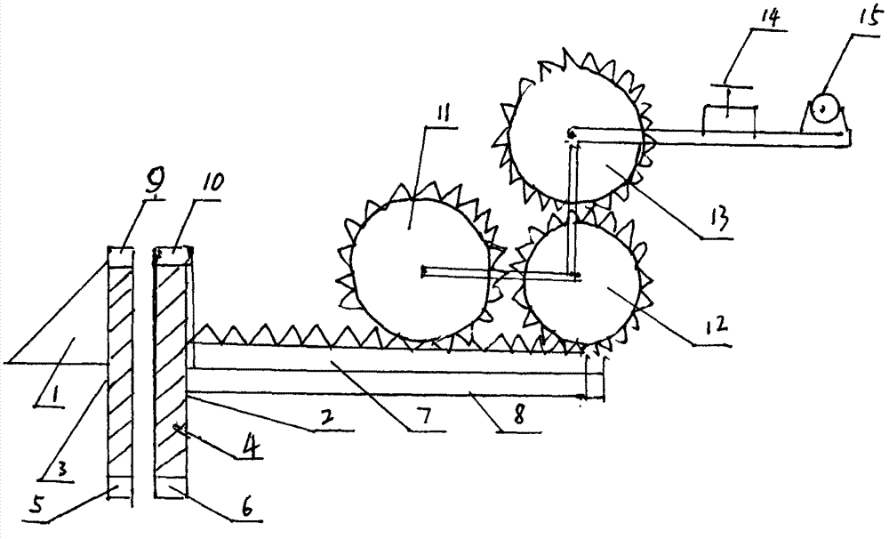
[0008] The present invention will be described in further detail below in conjunction with accompanying drawing embodiment, as appended figure 1 The electronic power ejection booster shown, its structural setting is that two triangular baffles 1 and the plane baffle 2 are arranged in parallel, and a plane push rod 7 is arranged perpendicular to the plane baffle 2, under the plane rack push rod 7 and The push rubber air cushion 8 is arranged in parallel, the rack push rod 7 is toothed and connected to the driven wheel 11, the driving wheel 11 is toothed and connected to the driven wheel 12, the driven wheel 12 is toothed and connected to the driving wheel 13, and the driving wheel 13 is connected to the motor through the transmission 14 15. The main body of the triangular baffle 1 is set as an electromagnet A3, the upper part is provided with a clamping electromagnet card A9, the lower part is provided with a coil A5, the main body of the plane baffle 2 is set as an electromagne...


PUM


Abstract

The invention discloses an electronic power catapult booster and aims at allowing an object to automatically run to a required stroke or position. The electronic power catapult booster is characterized in that a triangular retainer (1) and a planar retainer (2) are disposed in parallel, a planar rack push bar (7) is perpendicular to the planar retainer (2), a push rubber air cushion (8) is parallelly disposed below the planar rack push bar (7) and is in meshed connection with a driven wheel (11), the driven wheel (11) is in meshed connection with another driven wheel (12) which is in meshed connection with a driving wheel (13), the driving wheel (13) is connected to a motor (15) through a transmission (14), the triangular retainer (1) mainly comprises an electromagnet A (3) which is provided with an electromagnet clamp A (9), a coil (5) is arranged at the bottom of the electromagnet A (3), the planar retainer (2) mainly comprises an electromagnet B (4) provided with an electromagnet clamp B (10), and a coil B (6) is disposed at the bottom of the electromagnet B (4). The electronic power catapult booster is stable and safe, allows regular time and constant speed and can automatically run to the required stroke or position; the electronic power catapult booster is applicable to use with drying equipment.

Description

Technical field: [0001] The invention specifically relates to an electronic power ejection booster, which belongs to the technical field of mechanical equipment manufacturing. Background technique: [0002] The ejection booster uses the principle of electromagnet homosexual repulsion to start the engine A, and the low-speed gear drives the flywheel to fly. When the flywheel speed reaches a certain level, change to the medium-speed gear of A, and then change to the high-speed gear of A. After normal, The clutch B gear drives the rotating wheel to rotate, and the rotating wheel drives the teeth on the propulsion rod to push. The propulsion rod is pushed forward by the rubber air cushion on the rod head. Known, also do not have a kind of both can guarantee steady at present, safe, automatically enter drying equipment on time, have scientific and practical electronic power ejection booster again. Invention content: [0003] The object of the present invention is to provide an...

Claims


Application Information

Patent Timeline
IPC IPC(8): F26B25/00
Inventor 杜文王美英杜帅奇齐莉娟赵立芳
Owner 新昌县科博机械有限公司
Why Eureka
Try Eureka