
Large-relative-aperture high-precision refraction-reflection star sensor optical system

A star sensor and relative aperture technology, applied in the field of optical systems, can solve the problems of slow image refresh rate, long integration time, low incident light energy, etc. Effect of Entrance Pupil Diameter

Active Publication Date: 2015-04-08
CHANGCHUN INST OF OPTICS FINE MECHANICS & PHYSICS CHINESE ACAD OF SCI
View PDF8 Cites 4 Cited by
  • Summary
  • Abstract
  • Description
  • Claims
  • Application Information

AI Technical Summary

Problems solved by technology

[0003] In order to solve the problems in the prior art that the incident light energy received by the image detector per unit time is small, the integration time is long when the motion imaging is fixed, and the image refresh rate is slow; the adaptive spectral range is narrow; the imaging distortion is large and the authenticity is poor. Provide a high-precision catadioptric star sensor optical system with large relative aperture, large entrance pupil area, small deviation of the energy center of mass of the entire field of view, and low distortion. Reduce the integration time of the image detector of the star sensor, meet the requirements of fast attitude determination of the star sensor, expand the application range of the optical system of the star sensor, and overcome the defect of the low performance index of the existing technology of the transmissive star sensor

Method used


Image

  • Large-relative-aperture high-precision refraction-reflection star sensor optical system
  • Large-relative-aperture high-precision refraction-reflection star sensor optical system
  • Large-relative-aperture high-precision refraction-reflection star sensor optical system

Examples


Embodiment

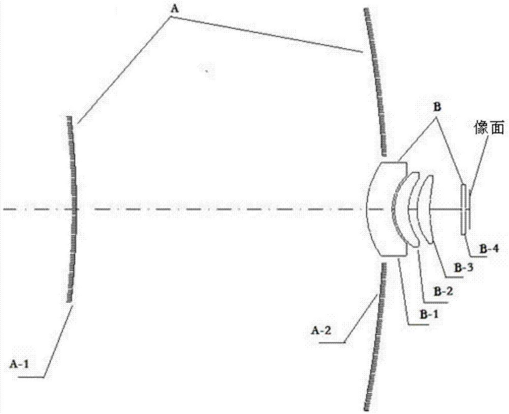
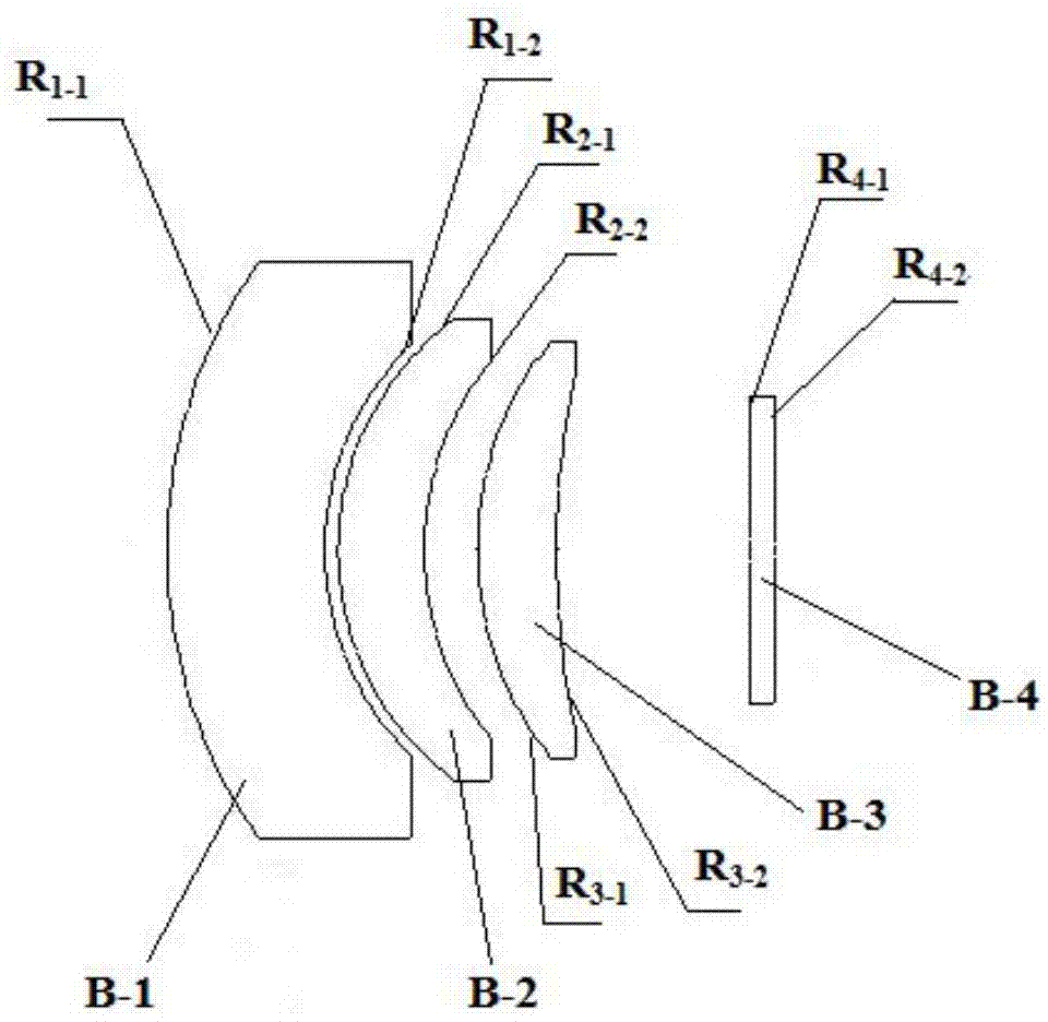
[0037] like figure 1 As shown, the front mirror group A with positive refractive power and the rear mirror group B with positive refractive power are respectively set according to the order of light incidence, and the front mirror group A is composed of secondary reflector A-1 and primary reflector A-2 composition, focal length f A '=247.63mm; the rear mirror group B is composed of a first convex-concave lens B-1, a second convex-concave lens B-2, a third convex-concave lens B-3 and parallel plate glass B-4, and the first convex-concave lens B-1, the second convex-concave lens B-2 and the third convex-concave lens B-3 are all spherical lenses with focal length f B '=141.811 mm.

[0038] The air gap between the front mirror group A and the rear mirror group B is 68.034mm.

[0039]The air separation between the secondary mirror A-1 and the primary mirror A-2 is 72 mm.

[0040] The air gap between the first lenticular lens B-1 and the second lenticular lens B-2 was 0.5 mm.

...


PUM


Abstract

The invention relates to a large-relative-aperture high-precision refraction-reflection star sensor optical system, which belongs to the technical field of optical systems, and overcomes the problems of the prior art. The optical system is provided with a front mirror group with positive focal power and a rear mirror group with a positive focal power, which are arranged in sequence according to the incidence direction of the light, wherein the front mirror group consists of a secondary reflecting mirror and a main reflecting mirror; the rear mirror group consists of a first convex-concave lens, a second convex-concave lens, a third convex-concave lens and parallel plate glass, and the first convex-concave lens, the second convex-concave lens and the third convex-concave lens are all spherical lenses; an air interval between the secondary reflecting mirror and the first convex-concave lens is 68.034, the air interval between the secondary reflecting mirror and the main reflecting mirror is 72mm, the air interval between the first convex-concave lens and the second convex-concave lens is 0.5mm, the air interval between the second convex-concave lens and the third convex-concave lens is 2.013mm, and the air interval between the third convex-concave lens and the parallel plate glass is 7.328mm.

Description

technical field [0001] The invention relates to a catadioptric star sensor optical system, which belongs to the technical field of optical systems. Background technique [0002] Star sensors have a variety of imaging models according to the wavelength range and detector type used. Their performance indicators are quite different. Most of them adopt the transmission type of full transmission lens. The focal length of the system is generally 20mm-60mm, and the effective entrance pupil diameter is generally 10mm-50mm. The incident light energy received by the image detector per unit time is less, and the motion imaging Attitude-time integration time is long, the image refresh rate is slow; the adaptive spectral range is narrow; imaging distortion is large, and the authenticity is poor. Contents of the invention [0003] In order to solve the problems in the prior art that the incident light energy received by the image detector per unit time is small, the integration time is...

Claims


Application Information

Patent Timeline
Patent Type & Authority Applications(China)
IPC IPC(8): G01C21/02
CPCG01C21/02
Inventor 刘伟奇吕博张大亮姜珊康玉思
Owner CHANGCHUN INST OF OPTICS FINE MECHANICS & PHYSICS CHINESE ACAD OF SCI
Learn More