Buried pipeline temperature measuring method
A technology for buried pipelines and temperature measurement, which is applied to thermometers, measuring devices, and heat measurement. It can solve problems such as low measurement accuracy, poor safety or stability, and high maintenance costs, and achieve investment savings, easy maintenance and operation, and prevent rainwater. entry effect
- Summary
- Abstract
- Description
- Claims
- Application Information
AI Technical Summary
Problems solved by technology
Method used
Image

Examples
Embodiment Construction
[0011] The technical solutions of the present invention will be further described below in conjunction with the accompanying drawings and embodiments.
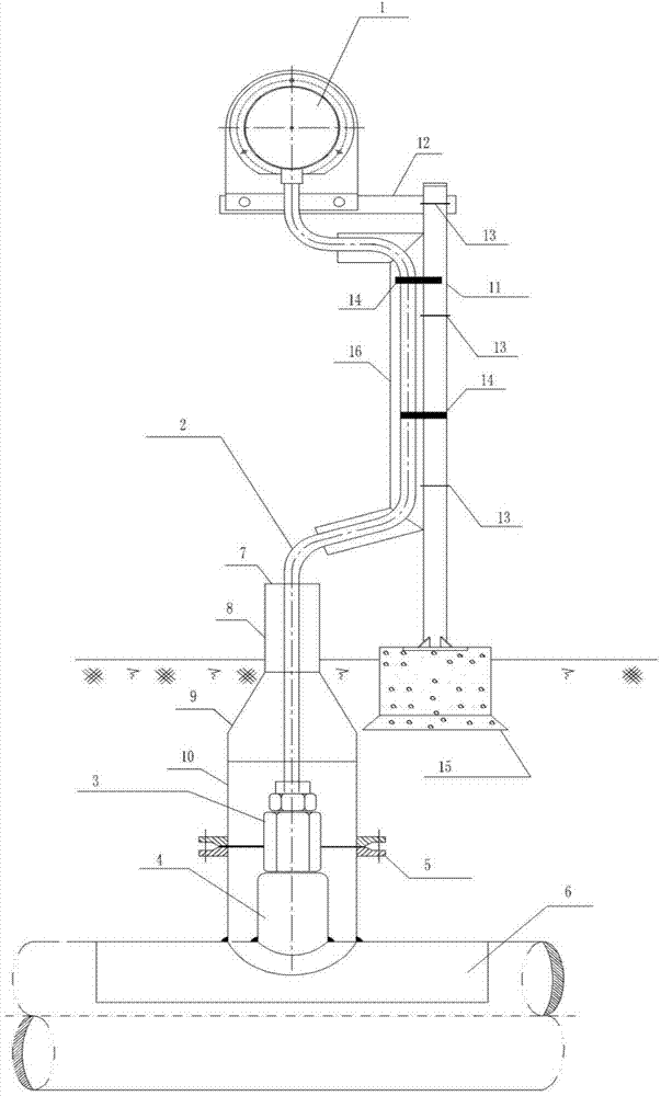
[0012] see figure 1 , the embodiment of the present invention provides a buried pipeline temperature measurement method, which consists of a plug-in thermometer 1, a capillary tube 2, a thermometer outer protective sleeve 3, a threaded boss 4, a protective steel pipe, a sealing block 7, a mounting bracket 11 and The cable trough box 16 is composed of, and the specific measurement process includes: welding the threaded boss 4 on the buried pipeline 6, the threaded end of the threaded boss 4 and the outer protective sleeve 3 of the thermometer are connected by threads; one end of the mounting bracket 11 passes through the concrete foundation 15 It is fixed on the ground, and the other end is fixed with a plug-in thermometer 1; the cable box 16 is fixed on the mounting bracket 11; The casing 3 is connected; the protective steel ...
PUM
 Abstract
Description
Claims
Application Information
PatSnap Eureka turns technology decisions into work you can execute. Powered by our Innovation Knowledge Graph, it runs expert workflows across engineering, life sciences, materials and intellectual property. Get your review-ready output in minutes.


