
A Composite Imaging Analog Optical System

An optical system and composite imaging technology, which is applied in the field of composite imaging analog optical systems, to meet the overall requirements and achieve the effect of small overall size

Active Publication Date: 2017-02-22
BEIJING ZHENXING METROLOGY & TEST INST
View PDF4 Cites 0 Cited by
  • Summary
  • Abstract
  • Description
  • Claims
  • Application Information

AI Technical Summary

Problems solved by technology

[0003] The purpose of the present invention is to overcome the deficiency that the prior art simply adopts the transmissive or reflective type and cannot meet the current new technical requirements, and provides a composite imaging analog optical system

Method used


Image

  • A Composite Imaging Analog Optical System
  • A Composite Imaging Analog Optical System
  • A Composite Imaging Analog Optical System

Examples


Embodiment Construction

[0031] Specific embodiments of the present invention will be described in detail below in conjunction with the accompanying drawings. In the following description, for purposes of explanation and not limitation, specific details are set forth in order to provide a thorough understanding of the invention. It will be apparent, however, to one skilled in the art that the present invention may be practiced in other embodiments that depart from these specific details.

[0032] It should be noted here that, in order to avoid obscuring the present invention due to unnecessary details, only the device structure and / or processing steps closely related to the solution according to the present invention are shown in the drawings, and the steps related to the present invention are omitted. Invent other details that don't really matter.

[0033] Embodiments of the present invention will be described below with reference to the drawings.

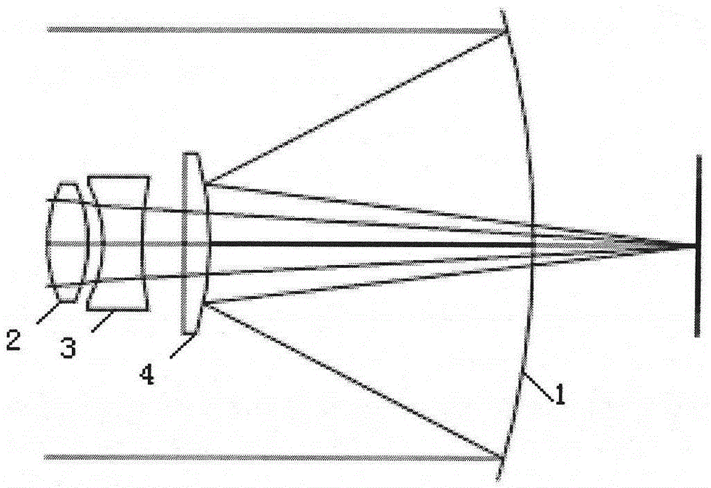
[0034] Such as figure 1As shown, a composite im...


PUM

PropertyMeasurementUnit
diameteraaaaaaaaaa
diameteraaaaaaaaaa
thicknessaaaaaaaaaa

Abstract

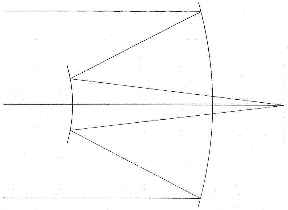
The invention provides a compound imaging simulation optical system which is mainly composed of a reflection-type infrared optical system and a transmission-type visible light and laser optical system. The compound imaging simulation optical system sequentially comprises a large-aperture reflecting mirror, a first lens, a second lens, and a third lens. By combining the reflection-type optical system and the transmission-type optical system and reasonably matching parameters of the lenses such as material, radius, distance and thickness, the imaging quality requirement (+ / -0.5 degrees) of the infrared optical system and the observation range requirement (+ / -5.5 degrees) of the visible light and laser optical system can be satisfied, and the performance demand of a three-in-one common-aperture optical system is ultimately achieved. The overall size of the whole system device is minimized, and the overall requirement of the whole system device is met.

Description

technical field [0001] The invention belongs to the field of multi-target characteristic simulation and relates to a composite imaging simulation optical system. Background technique [0002] In the field of military applications, the electromagnetic environment of the modern battlefield is becoming more and more complex, which puts forward new technical and tactical requirements for precision-guided weapon systems. Weapon systems using traditional single-guidance modes such as infrared, visible light, and laser have defects and use limitations, and it is difficult to operate in a complex environment. Under the conditions of battlefield background and strong electromagnetic interference environment, to quickly and accurately intercept and track targets, complete combat missions, and develop multi-spectrum or multi-system compound homing guidance is increasingly becoming an important way to improve the hit probability of various precision guided weapons. In order to meet the ...

Claims


Application Information

Patent Timeline
Patent Type & Authority Patents(China)
IPC IPC(8): G02B27/00G02B1/11
CPCG02B1/11G02B27/00
Inventor 任小婉张玉国孙红胜
Owner BEIJING ZHENXING METROLOGY & TEST INST
Learn More