Optical module and reflective display device

A technology of optical modules and optical films, applied in optics, optical components, nonlinear optics, etc., can solve the problems of low contrast and abnormal display of reflective LCDs

Active Publication Date: 2015-04-08
BOE TECH GRP CO LTD
View PDF6 Cites 19 Cited by
  • Summary
  • Abstract
  • Description
  • Claims
  • Application Information

AI Technical Summary

Problems solved by technology

[0004] On this basis, as figure 1 As shown, since both sides of the light guide plate 101 can emit light, and they all belong to a large-angle light emission (that is, the direction perpendicular to the liquid crystal display panel is the normal direction, and the angle at which the light deviates from the normal direction is relatively large), so the sid...

Method used


Image

  • Optical module and reflective display device
  • Optical module and reflective display device
  • Optical module and reflective display device

Examples


Embodiment Construction

[0034] The following will clearly and completely describe the technical solutions in the embodiments of the present invention with reference to the accompanying drawings in the embodiments of the present invention. Obviously, the described embodiments are only some, not all, embodiments of the present invention. Based on the embodiments of the present invention, all other embodiments obtained by persons of ordinary skill in the art without making creative efforts belong to the protection scope of the present invention.

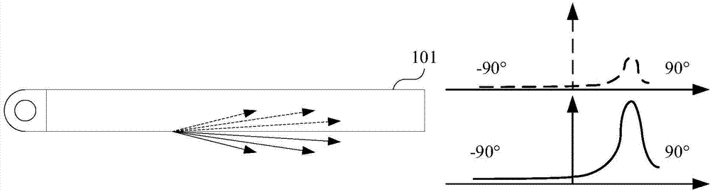
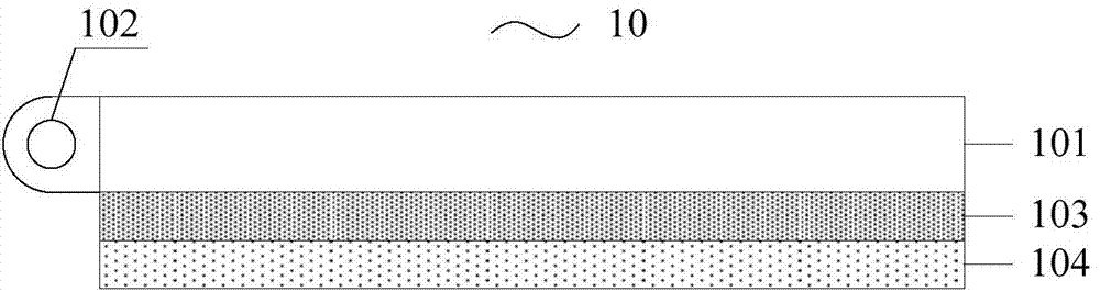
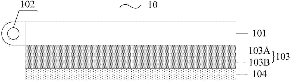
[0035] Embodiments of the present invention provide an optical module 10, such as figure 2 and image 3 As shown, the optical module 10 is arranged on the display side of the display panel; the optical module 10 includes a light guide plate 101, a light emitting unit 102 arranged on the side of the light guide plate 101, and an The optical film 103 and the scattering film 104 between the display panels; wherein, the optical film 103 is arranged on the side c...


PUM

PropertyMeasurementUnit
Angleaaaaaaaaaa
Angleaaaaaaaaaa
Angleaaaaaaaaaa

Abstract

The embodiment of the invention provides an optical module and a reflective display device and relates to the technical field of display. The optical module and the reflective display device can be used for improving the display effect under a dark environment and increasing the contrast ratio of a displayer. The optical module is arranged at a display side of a display panel and comprises a light guide plate, a light emitting unit arranged on the side surface of the light guide plate, and an optical film and a scattering film which are arranged between the light guide plate and the display panel, wherein the optical film is arranged close to one side of the light guide plate and is used for reducing the incident angle of incident light; the scattering film is arranged close to one side of the display panel and is used for scattering the incident light. The optical module is used for manufacturing a display device.

Description

technical field [0001] The invention relates to the field of display technology, in particular to an optical module and a reflective display device. Background technique [0002] Reflective LCD (Liquid Crystal Display, liquid crystal display) is to realize the display function by reflecting light under the condition of sufficient ambient light by setting a reflective layer under the liquid crystal display panel (that is, the side where the liquid crystal layer is away from the light-emitting side). However, traditional reflective LCDs are highly dependent on ambient light and cannot display in low light conditions. [0003] In order to solve the above problems, in the prior art, a light guide plate is arranged above the liquid crystal display panel (that is, the side of the liquid crystal layer close to the light-emitting side), and a light-emitting unit is arranged on the side of the light guide plate, so that the reflective LCD has insufficient ambient light. It can also ...

Claims


Application Information

Patent Timeline
IPC IPC(8): G02F1/1335G02F1/13357
CPCG02F1/133615G02F1/13362G02F1/133607G02B6/0051G02B6/0056G02B6/0088G02F1/133616G02B6/0053
Inventor 秦广奎王新星祝明杨泽洲谭纪风
Owner BOE TECH GRP CO LTD
Why Eureka
Try Eureka