Objective lens

a technology of objective lens and lens body, applied in the field of compact lenses, can solve the problems of reducing the sensitivity of the lens to dramatic temperature changes, and achieve the effects of reducing the incidence angle, reducing manufacturing costs, and optimum combination of imaging quality

Inactive Publication Date: 2007-02-06
NING ALEX
View PDF8 Cites 28 Cited by
  • Summary
  • Abstract
  • Description
  • Claims
  • Application Information

AI Technical Summary

Benefits of technology

[0010]The above-noted problems, and others, are overcome in accordance with this invention with an objective lens for digital cameras that may also be incorporated into other devices such as a cell-phones, personal digital assistants and the like. The objective lens of this invention is extremely compact and has have a short length from the front element surface to the imaging plane, has a total of four or more lens elements and it has excellent optical characteristics.
[0011]The objective lens of the present invention comprises three optical elements with each element serving a distinct optical function. The first optical element is a lens group and it can consist of from two lens element to three lens elements. The lens group has a positive optical power. In a first embodiment, the lens group is a doublet and has two lens elements. In a second embodiment, the lens group is a triplet and has three lens elements. In a third embodiment, the lens group is also a triplet and has three lens elements, two of which are bonded together with optical cement. A middle lens element follows the lens group and is a single lens element with a meniscus shape (i.e., one side is concave and the other is convex) with the concave side facing the first lens group. This group will be identified as the middle lens element. The third lens group is also a single element with a positive power. This group will be identified as the final lens element. The primary function of the third element or final lens is to reduce the angle of incidence of off-axis rays to the image plane. The primary function of the middle lens element 36 is to reduce the off-axis optical aberrations of the lens group 34 and that of the final lens element 38 allowing the objective lens to achieve high image quality. The surface profiles of all of the lens element can be aspherical to gain further performance (i.e. surfaces that are not spherical but described by a general mathematical equation). An electronic imaging sensor 14 is spaced at a suitable distance from the final lens element.
[0012]In the preferred embodiment, an IR cut-off coating is also applied to the image surface of the final lens element to produce an integrated imaging lens with IR cut-off function. This eliminates the need for a separate IR cut-off filter in addition to the lens, thus making the entire optical assembly less costly to manufacture.
[0013]In the preferred embodiment, the lens group elements are all made of glass. The use of glass material for the lens elements reduces the sensitivity of the lens to dramatic temperature changes. A reduced temperature sensitivity provides for stabilized performance such as when a camera using the objective lens is moved from an exterior location into an interior where a substantial temperature difference exists between the two locations.
[0016]A further object is to provide a digital camera lens having an extremely short length from the front surface of the lens to the image plane, and having a reduced angle of incidence for the off-axis rays on the image plane.
[0017]Yet another object is to provide a digital camera lens having an integrated IR cut-off coating to provide an optimum combination of imaging quality, small F-stop, and low manufacturing cost.

Problems solved by technology

The use of glass material for the lens elements reduces the sensitivity of the lens to dramatic temperature changes.

Method used


Image

  • Objective lens
  • Objective lens
  • Objective lens

Examples


second embodiment

[0058]Table 2 has a first and second set of six rows each. Table 2 is used in connection with Table 1 to characterize the middle lens element surfaces 44 and 46 for the second embodiment using the doublet of FIG. 2b. The first or top set provides the D, E, F and G coefficients for a prescription in accordance with Equation 1 for middle lens element object surface 44. The second or lower set provides the D, E, F and G coefficients for a prescription in accordance with Equation 1 for the middle lens element image surface 46. Coefficients are not provided by rows 5 and 6 for coefficients H and I. These coefficients would be initialized to be zero.

[0059]

TABLE 2Aspheric coefficients for surfaces of the middle lens element 36RowSurface 44 of the middle lens element 36,an EVENASPH Lens Surface1D−0.155454972E−0.16930173F 0.589310654G−1.00120365H6ISurface 44 of the middle lens element 36,an EVENASPH Lens Surface1D−0.0268012692E 0.0009468343F−0.0002215664G−7.01E−055H6I

[0060]Row 6 provides a p...

first embodiment

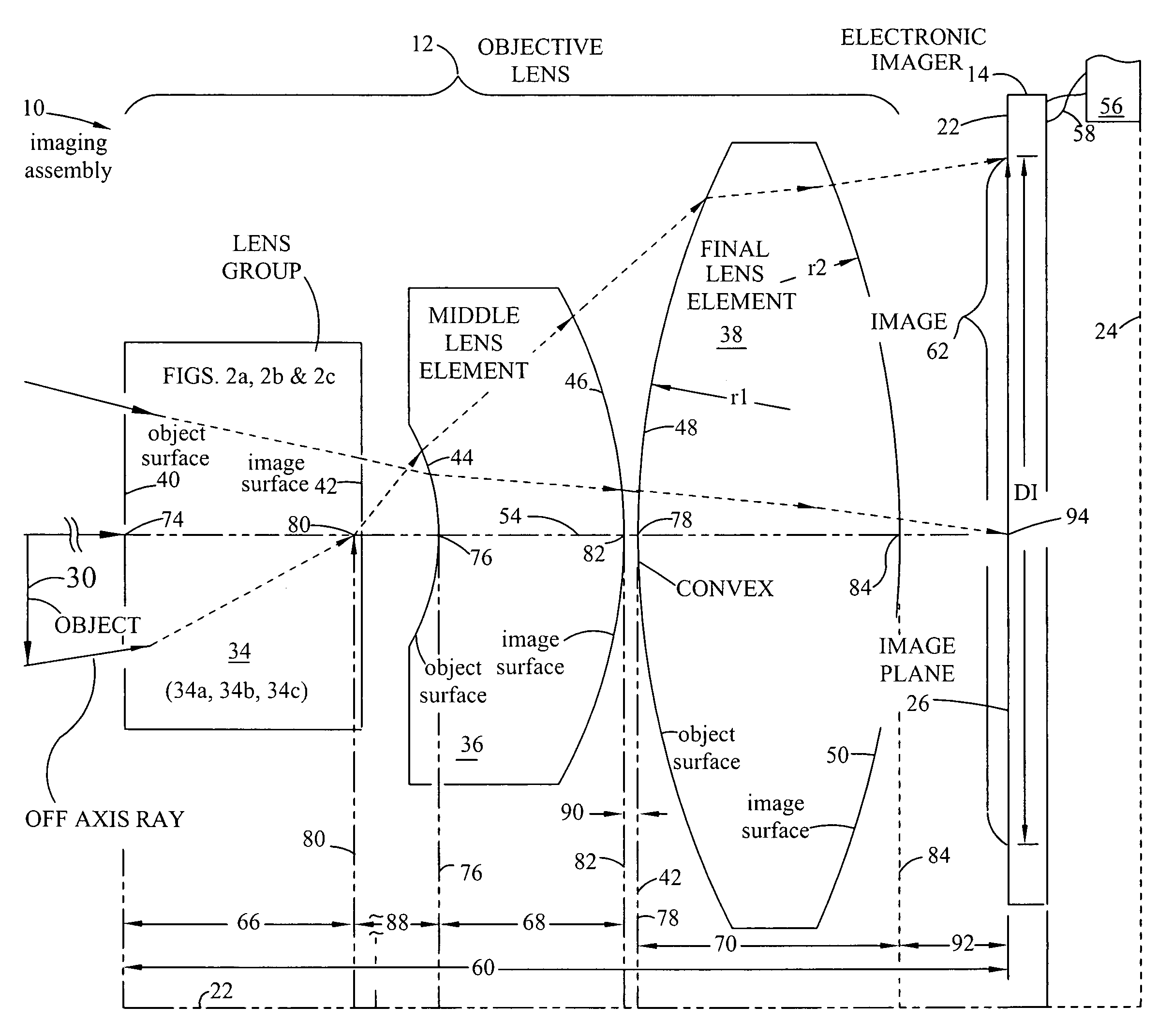
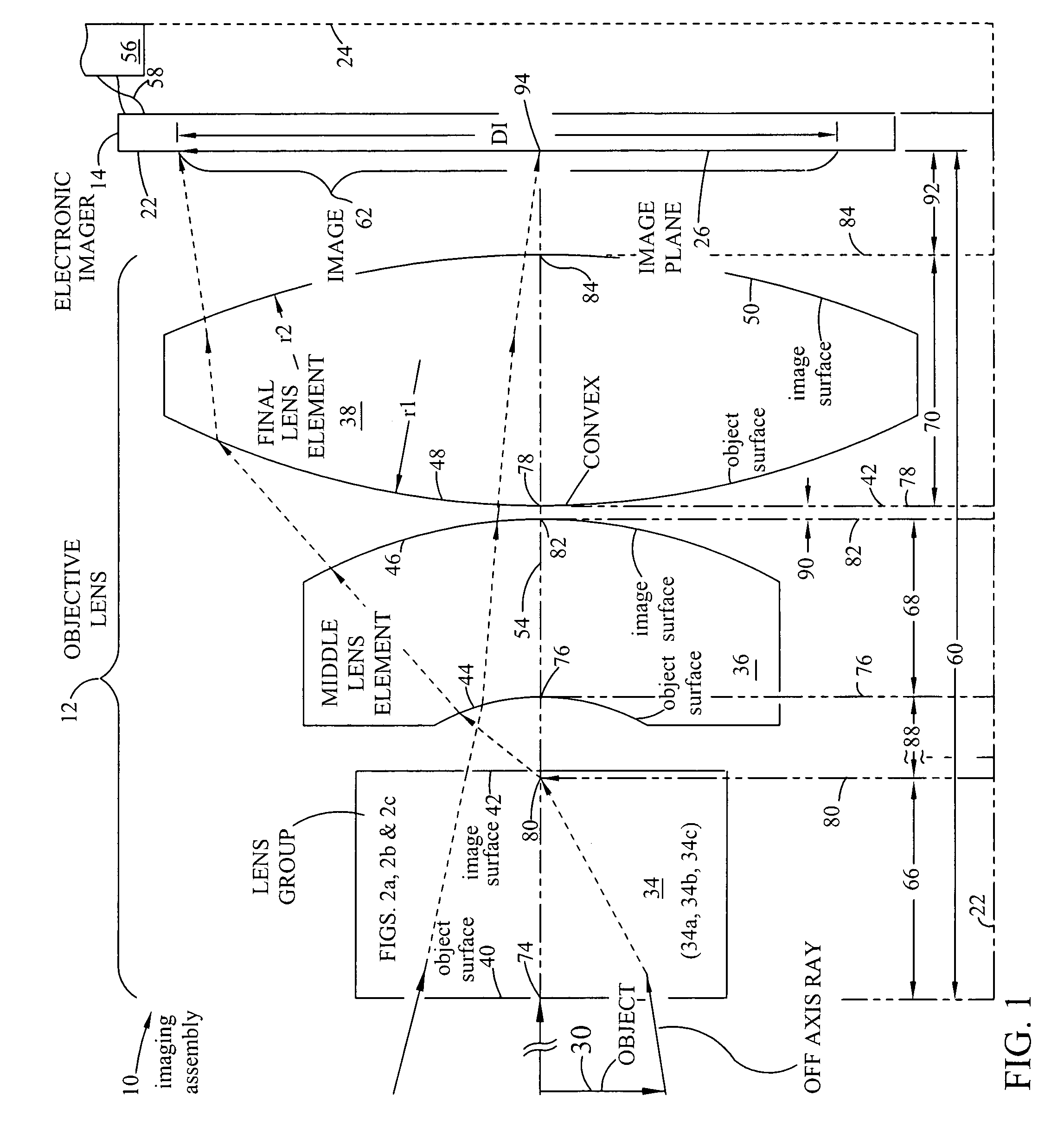
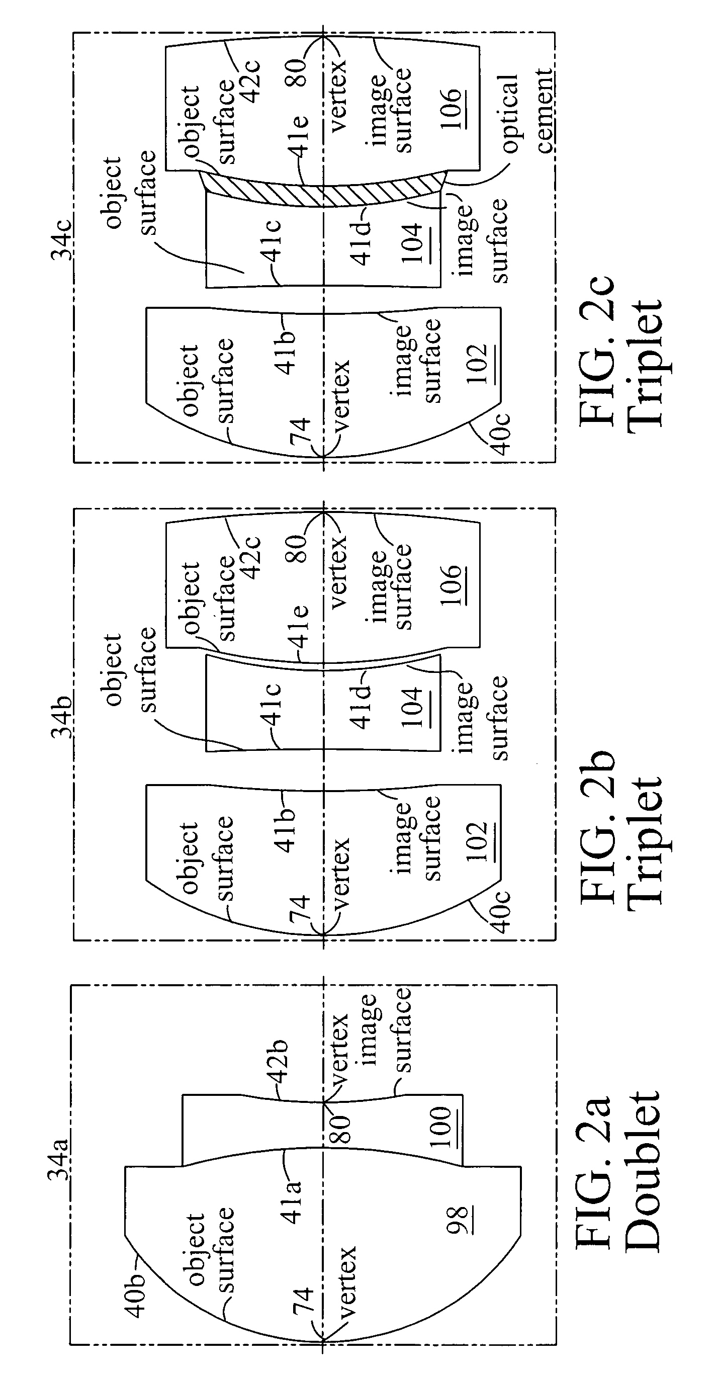
[0065]Table 3 provides a second preferred embodiment of the present invention. The surfaces are all STANDARD. There are no aspheric surfaces. The triplet lens within phantom box 34b is formed with three separate lenses as shown in FIG. 2b. When formed, the lens group is substituted for the lens group 34 in FIG. 1. A prescription for its surfaces is provided in rows 1, 2, 3, 4, 5, 6 and 7 of Table 3. As in the case of the first embodiment, the lens group object surface (40c) collects rays of light from the object 30 shown schematically in FIG. 1. FIG. 2b shows the triplet formed from first lens elements 102, second lens element 104 and third lens element 106. The three lens surfaces are characterized as STANDARD, therefore, each of the three surfaces are spherical surfaces.

[0066]Row 2 of Table 3 shows that the radius of surface 40c is 2.25801 mm and the thickness of lens element 102 is 1.058656 mm.

[0067]Row 3 of Table 3 shows that the radius of surface 41b is 7.551701. The distance t...


PUM


Abstract

The compact imaging assembly has an electronic imager and an objective lens with a focal length fo. The objective lens receives light and forms an image of the object on the imager's image plane. The image plane has a maximum effective dimension DI. The objective lens has a first lens group comprising two to three elements with an object surface facing the object and an image surface facing an image plane. The objective lens also has a middle lens element with a concave object surface that is facing the lens group image surface, and a final lens element that has a positive power. The distance from the lens group object surface to the image plane is TT. The lens group, the middle lens and the final lens elements are coaxially aligned and on an optical axis normal to the image plane.

Description

[0001]This is a Continuation-In-Part Application from earlier application Ser. No. 10 / 620,676 filed Jul. 16, 2003, now abandoned and from non-provisional patent application Ser. No. 10 / 666,640 filed Sep. 18, 2003, now abandoned and from provisional application Ser. No. 60 / 591,496 filed Jul. 26, 2004 all having a common inventorFIELD OF THE INVENTION[0002]This invention relates to compact lenses for digital camera applications and, in particular, to lenses for very compact digital cameras such as compact lenses that can be incorporated into a cellular telephones, personal digital assistants, or other very small electronic devices.[0003]BACKGROUND OF THE INVENTION[0004]Digital cameras utilizing high-resolution electronic imaging sensors require high resolution optics. For the consumer market, it is important that such lenses be produced in high volume and inexpensively. For use in very compact digital cameras, and cameras that might be incorporated into devices such as palm-sized comp...

Claims


Application Information

Patent Timeline
Patent Type & Authority Patents(United States)
IPC IPC(8): G02B13/18G02B9/12G02B13/00
CPCG02B13/006G02B13/0035
Inventor NING, ALEX
Owner NING ALEX
Why Eureka
Try Eureka