Method for producing joints for transmitting rotary motion

A technology of rotary motion and connecting parts, applied in the direction of anti-centrifugal force rotating parts, engine components, applications, etc., can solve the problems of complex production of pivot pins, and achieve the effects of weight saving, great flexibility, and high degree of automation

Active Publication Date: 2018-07-06
THYSSENKRUPP STEEL EURO AG
View PDF18 Cites 0 Cited by
  • Summary
  • Abstract
  • Description
  • Claims
  • Application Information

AI Technical Summary

Problems solved by technology

Overall, the production of the pivot pin is thus likewise complicated

Method used


Image

  • Method for producing joints for transmitting rotary motion
  • Method for producing joints for transmitting rotary motion
  • Method for producing joints for transmitting rotary motion

Examples


Embodiment Construction

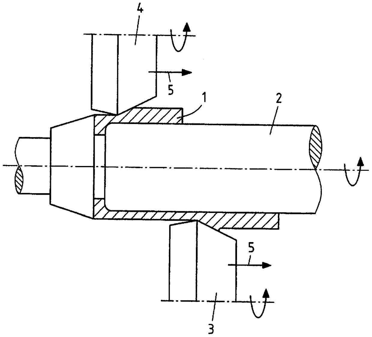
[0020] Now figure 1 In a schematic view, the sequence of fluid forming or fluid diversion of a tubular blank 1 is shown, which can be provided, for example, via discs or pipe sections. The inner mandrel 2 predetermines the shape on which identical rotating pressing tools 3 , 4 , only half shown in each case, press against the blank. Here the pressing tools 3 , 4 travel in the advancing direction 5 and are moved, for example to correspond to the contour of the mandrel 2 so that the blank 1 is deformed accordingly. On the basis of this production principle, any rotationally symmetrical shape, especially thickened and conical sections provided in a radial circumferential manner, figure 1 It is readily conceivable to produce the extrusion tools 3 , 4 shown. Any other shape can be produced in the blank by extrusion via an eccentrically rotating tool used instead of the extrusion tools 3 , 4 .

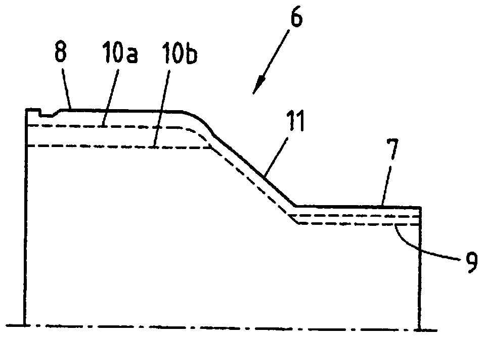
[0021] For example, figure 2 A first exemplary embodiment of a connection piece 6 a...


PUM


Abstract

A method may be used to produce a connecting element for transmitting rotational movements, wherein the connecting element has a joint outer part or flange and a connecting pin. The object of providing a method for producing a connecting element with a joint outer part or flange and a connecting pin, with which method weight-optimized connecting elements can be produced in a simple manner, is achieved in that a round-plate-like or tubular blank is deformed by flow forming or flow turning to form the connecting element.

Description

technical field [0001] The invention relates to a method for producing a connecting part for transmitting a rotational movement, wherein the connecting part has a joint outer part or flange and a connecting pin. The invention also relates to a connection piece with a joint outer part or flange and a connection pin. Background technique [0002] Connecting members such as connecting pins are required to connect the rotary shafts to each other. Connections of the type considered are used for constant velocity joints, tripod joints and universal joints in order to connect non-parallel rotating spindles to each other in a form-fitting manner, whereby a rotary motion can be transmitted from one spindle to Another spindle. Connecting pins are conventionally manufactured from steel or other metals. A connecting pin manufactured from a blank together with the joint outer part is also referred to as a pivot pin. Connecting pins are used to connect joints or articulated shafts to,...

Claims


Application Information

Patent Timeline
Patent Type & Authority Patents(China)
IPC IPC(8): B21D22/16B21D53/28B21D53/84F16D1/033F16D3/10B21K1/76B21H5/02
CPCB21D22/16B21D53/28B21D53/84B21H5/025F16D3/223F16D2250/0023F16D1/076F16D2003/22326F16D2300/18Y10S464/906Y10T29/49696F16D3/16
Inventor 米夏埃尔·霍弗特
Owner THYSSENKRUPP STEEL EURO AG
Why Eureka
Try Eureka