Cam driving type compressing clamp for shaft workpieces

A shaft-type workpiece and driving technology, which is applied in the direction of manufacturing tools, metal processing machinery parts, clamping, etc., can solve the problems of high labor intensity for operators, failure to complete automatically, and low degree of automation, so as to facilitate popularization, use, and production The effect of low cost and high degree of automation

Inactive Publication Date: 2015-04-15
XIAN ZHONGZHI HUIZE PHOTOELECTRIC TECH
View PDF0 Cites 12 Cited by
  • Summary
  • Abstract
  • Description
  • Claims
  • Application Information

AI Technical Summary

Problems solved by technology

Under the guide part of the three claws on the three-jaw chuck, there are threads that mesh with the plane threads on the back of the bevel gear. When the small bevel gear is turned with a wrench through the square hole, the bevel gear rotates, and the plane threads on the back simultaneously Drive the three jaws to approach or withdraw from the center to clamp workpieces with different diameters. However, if the three-jaw chuck is used for a long time, the chuck will wear out, and the three jaws will also appear bell-mouthed, making the three jaws deviate from the chuck. In addition, when using the three-jaw chuck, the operator must manually clamp the workpiece, which cannot be done automatically. The operator has high labor intensity, low degree of automation, and low production efficiency.

Method used


Image

  • Cam driving type compressing clamp for shaft workpieces

Examples


Embodiment Construction

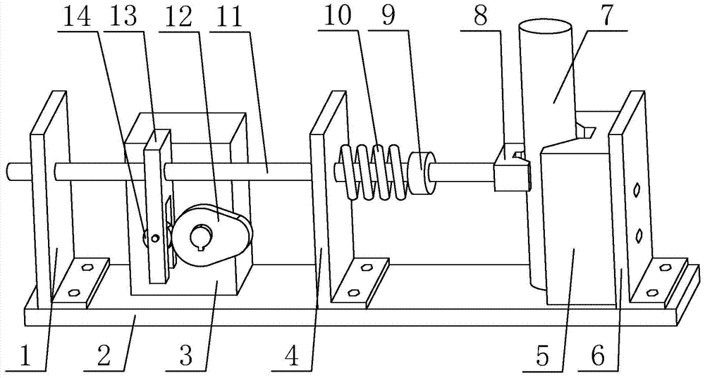
[0021] Such as figure 1 A cam-driven shaft workpiece pressing fixture shown includes a base plate 2, a power box 3 fixedly installed on the upper side of the base plate 2, and a power box 3 fixedly installed on the upper side of one end of the base plate 2 through an L-shaped baffle plate 6. The V-shaped pad 5 and the V-shaped pressing head 8 that is used to compress the workpiece 7 in cooperation with the V-shaped pad 5 are characterized in that: it also includes a fixed installation on the power output shaft of the power box 3 for driving The cam 12 that the push rod 11 moves back and forth in the horizontal direction; the upper side of the bottom plate 2 is slidingly installed with the push rod 11 through the L-shaped support plate 1 and the L-shaped support plate 2 4 parallel to each other, and the middle part of the push rod 11 is fixedly installed There is a roller frame 13, the roller frame 13 is provided with a roller 14 used in conjunction with the cam 12, the V-shape...


PUM


Abstract

The invention discloses a cam driving type compressing clamp for shaft workpieces. The compressing clamp comprises a bottom plate, a power box, a V-shaped base plate and a V-shaped compressing head and further comprises a cam for driving a pushing rod to move front and back in the horizontal direction; the pushing rod is arranged on the upper side of the bottom plate through a first L-shaped supporting plate and a second L-shaped supporting plate in a sliding manner; a roller frame is fixedly arranged in the middle of the pushing rod; a roller used in cooperation with the cam is arranged on the roller frame; the V-shaped compressing head is fixedly arranged at one end of the pushing rod, and a spring retaining plate is fixedly arranged at the position, between the V-shaped compressing head and the second L-shaped supporting plate, of the pushing rod; and a compressing spring is arranged between the spring retaining plate and the second L-shaped supporting plate. The cam driving type compressing clamp has the advantages of being reasonable in design, high in automation degree, easy and convenient to operate, low in labor intensity, long in service life, wide in application range, low in production cost and convenient to use and popularize.

Description

technical field [0001] The invention belongs to the technical field of mechanical processing, and relates to a compression fixture, in particular to a cam-driven compression fixture for machining shaft workpieces. Background technique [0002] At present, in the machining process of shaft workpieces, the most commonly used clamping tool is a three-jaw chuck because the outer contour of the shaft workpiece has a certain radian. The three-jaw chuck is composed of a chuck body, movable jaws and jaw driving mechanism. Under the guide part of the three claws on the three-jaw chuck, there are threads that mesh with the plane threads on the back of the bevel gear. When the small bevel gear is turned with a wrench through the square hole, the bevel gear rotates, and the plane threads on the back simultaneously Drive the three jaws to approach or withdraw from the center to clamp workpieces with different diameters. However, if the three-jaw chuck is used for a long time, the chuck ...

Claims


Application Information

Patent Timeline
IPC IPC(8): B23Q3/06
CPCB23Q3/06
Inventor 侯鹏
Owner XIAN ZHONGZHI HUIZE PHOTOELECTRIC TECH
Why Eureka
Try Eureka