Spiral forced feeding device

A technology of forced feeding and spiral, which is applied in the field of feeding devices, can solve the problems of reducing production efficiency, affecting the smooth progress of production, shutting down and clearing maintenance, etc., to ensure uninterrupted continuous feeding, avoid bridging problems, and ensure smooth progress Effect

Inactive Publication Date: 2015-04-15
GUANGDONG DESIGNER MASCH CO LTD
View PDF7 Cites 5 Cited by
  • Summary
  • Abstract
  • Description
  • Claims
  • Application Information

AI Technical Summary

Problems solved by technology

Because the recycled materials are rough, irregular in shape and large in particle size, and in order to prevent the feeding screw from arching the plastic upward into the storage funnel, the feeding port of the feeding cylinder is generally designed to be small, so that the recycled materials often get s

Method used


Image

  • Spiral forced feeding device
  • Spiral forced feeding device

Examples


Embodiment Construction

[0016] Further description will be given below in conjunction with the accompanying drawings and preferred embodiments of the present invention.

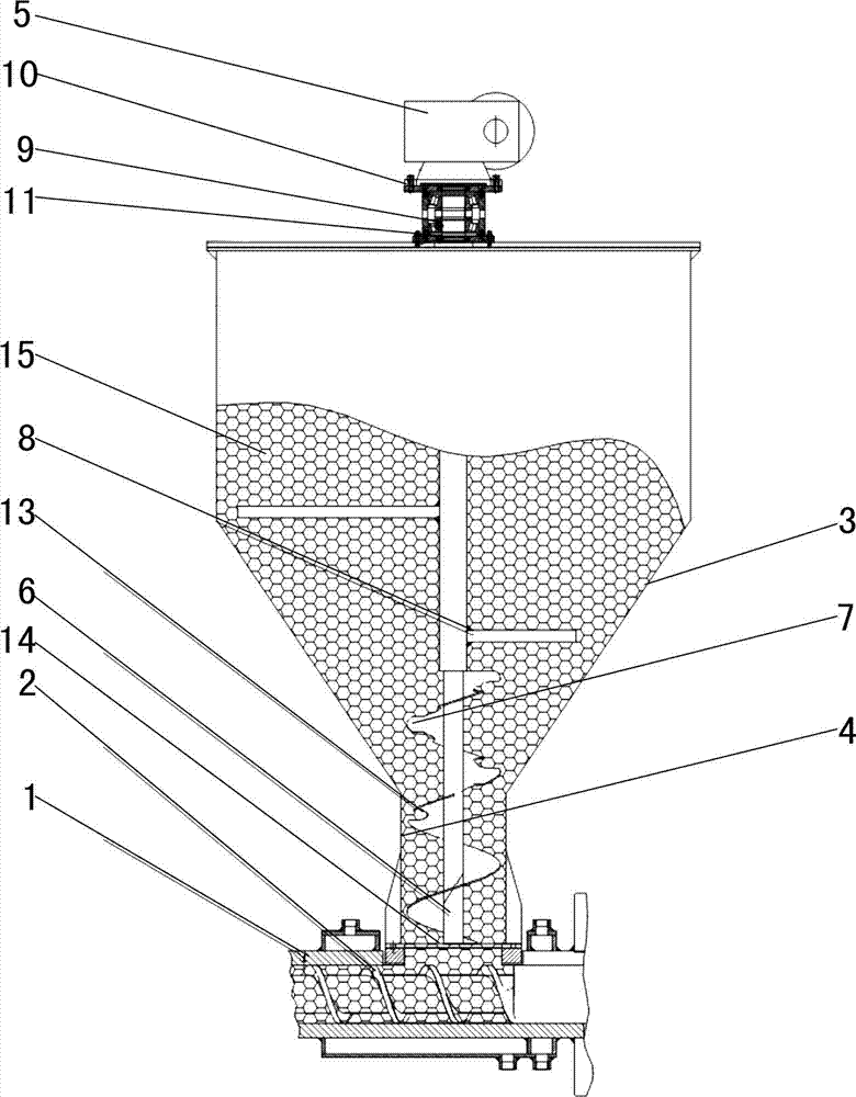
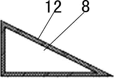
[0017] Such as figure 1 and figure 2 As shown, this screw forced feeding device includes a feeding cylinder 1, a feeding screw 2, a feeding motor ( figure 1 Not shown in), storage funnel 3, blanking barrel 4, propulsion motor 5, propulsion shaft 6, screw propulsion blade 7, two anti-bridging shafts 8, bearing 9, upper washer 10 and lower washer 11, anti-frame The cross section of the bridge shaft 8 has a slope 12 inclined from top to bottom, and the edge of the screw propulsion blade 7 is provided with a plurality of pressure relief ports 13, and the pressure relief port 13 is an arc-shaped gap opened on the edge of the screw propulsion blade 7; The feeding screw 2 is installed in the feeding barrel 1, the feeding screw 2 is in contact with the inner wall of the feeding barrel 1, and the feeding motor is connected with one end of...


PUM


Abstract

The invention relates to a spiral forced feeding device. The spiral forced feeding device comprises a material conveying barrel, a material conveying screw, a material conveying motor, a material storage hopper, a material falling barrel, a propulsion motor, a propulsion shaft, a spiral propulsion blade and an anti-bridging shaft, wherein the material conveying screw is mounted in the material conveying barrel; the material conveying motor is in transmission connection with the material conveying screw; a charging opening is formed in a barrel body of the material conveying barrel; a material falling opening of the material storage hoper is communicated and connected with the charging opening through the material falling barrel; the upper end of the propulsion shaft is rotatably mounted at the top of the material storage hopper; the propulsion shaft is positioned in the material storage hopper, and the lower end of the propulsion shaft extends to the charging opening; the propulsion motor is in transmission connection with the propulsion shaft; the spiral propulsion blade is mounted at the lower part of the propulsion shaft; the upper part of the spiral propulsion blade is positioned in the material storage hopper, and the lower part of the spiral propulsion blade is positioned in the material falling barrel; the anti-bridging shaft is mounted at the upper part of the propulsion shaft.

Description

technical field [0001] The invention relates to a feeding device, in particular to a screw forced feeding device. Background technique [0002] The feeding device of the current sheet extruder generally includes a feeding barrel, a feeding screw, a feeding motor and a storage funnel. The feeding screw is installed in the feeding barrel, and the feeding screw is in close contact with the inner wall of the feeding barrel. One end is transmission-connected, and the body of the feeding cylinder is provided with a feed port, and the discharge port of the storage funnel communicates with the feed port. The plastic granules in the storage funnel fall into the feeding barrel by their own gravity, and under the push of the feeding screw, the plastic granules are sent out from one end of the feeding barrel to complete the feeding of the sheet extruder. [0003] However, with the advancement of extrusion technology and technology, as well as the control of production costs, waste recy...

Claims


Application Information

Patent Timeline
IPC IPC(8): B29C47/10
CPCB29C48/288
Inventor 李意明罗庆青叶镇波陈诗煌
Owner GUANGDONG DESIGNER MASCH CO LTD
Why Eureka
Try Eureka