sewing system

A technology of a control unit and a sewing machine, which is applied in the field of sewing systems, and can solve the problems of inability to perform simultaneous and efficient sewing, etc.

Inactive Publication Date: 2017-04-12
BROTHER KOGYO KK
View PDF7 Cites 0 Cited by
  • Summary
  • Abstract
  • Description
  • Claims
  • Application Information

AI Technical Summary

Problems solved by technology

Therefore, multiple sewing machines may not be able to simultaneously perform the sewing operations of multiple sewing processes, thereby making it impossible to sew efficiently.

Method used


Image

  • sewing system
  • sewing system
  • sewing system

Examples


Embodiment Construction

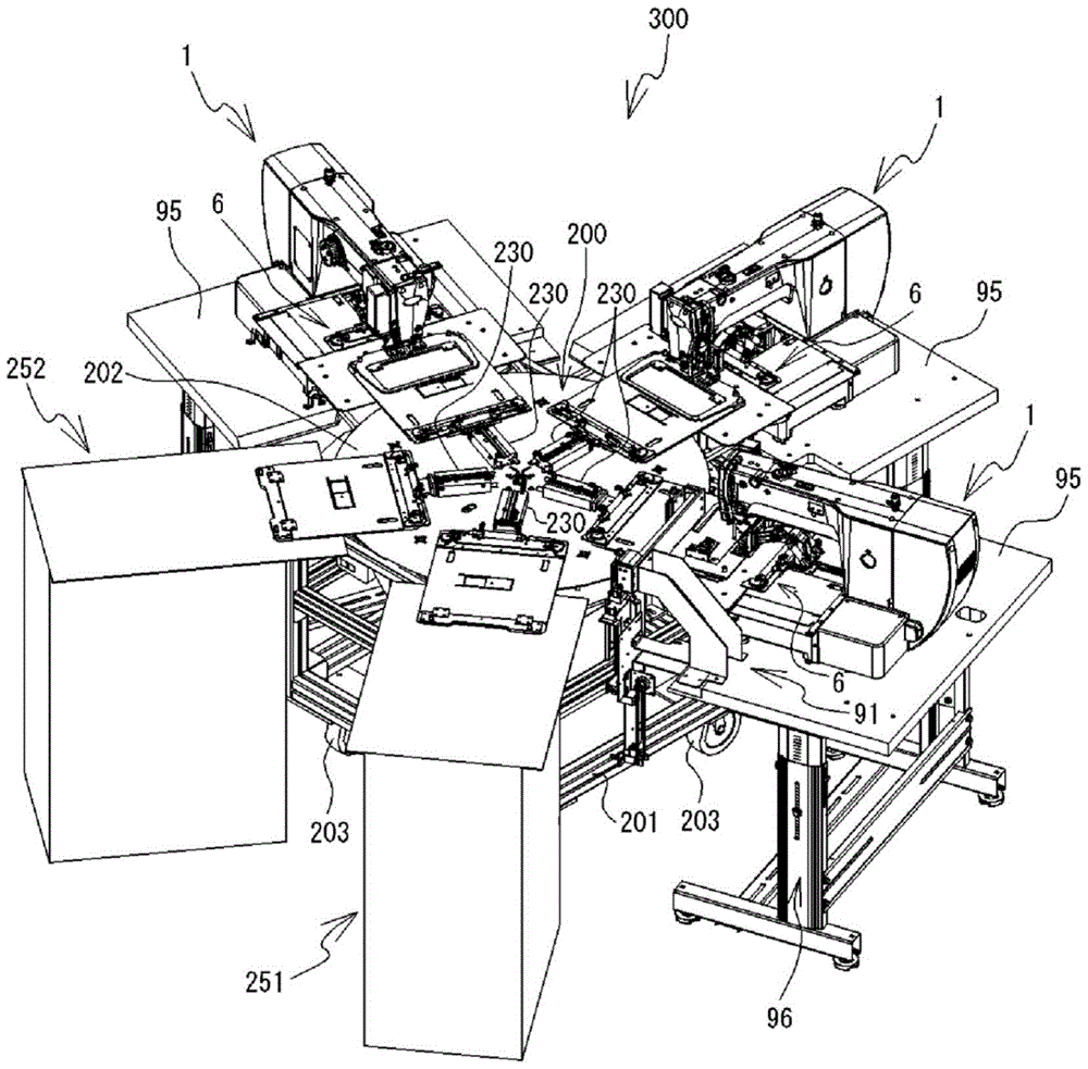
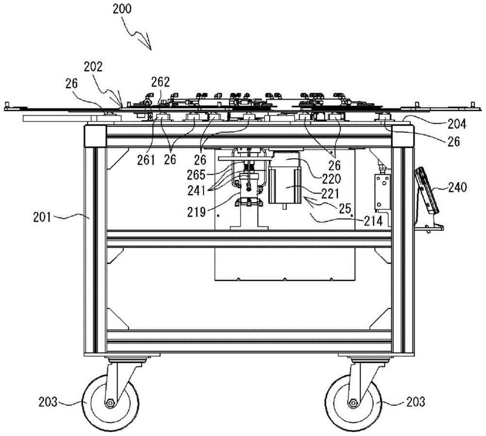
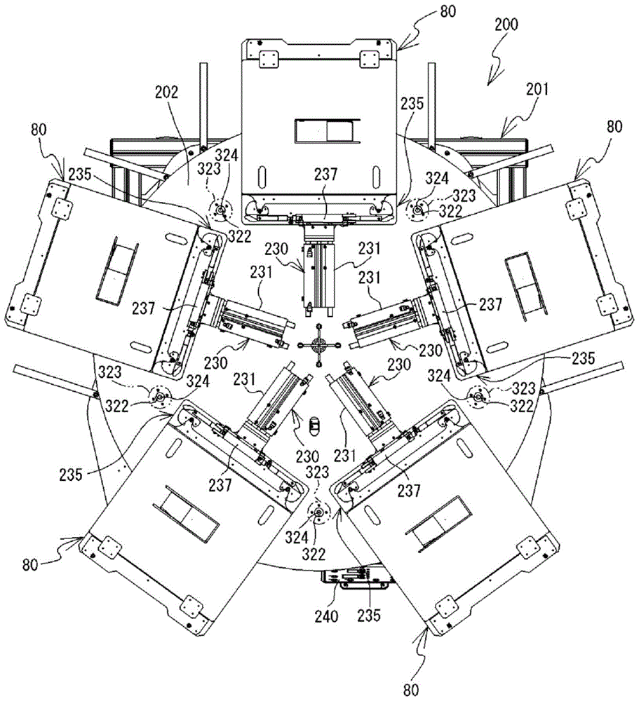
[0036] A first embodiment of the present invention will be described with reference to the drawings. refer to Figure 1 ~ Figure 4 A schematic configuration of the sewing system 300 including the sewing machine 1 will be described. Figure 4 The left oblique lower side, the right oblique upper side, the left oblique upper side, and the right oblique lower side are the front side, the rear side, the left side, and the right side of the sewing machine 1 included in the sewing system 300 . In the following description, left and right, front and rear, and up and down indicated by arrows in the figure are used. The sewing system 300 is arranged with a plurality of (three in this embodiment) sewing machines 1 and two consoles 251 and 252 at equal intervals around the holding board supply device 200, and the plurality of sewing machines 1 and the two consoles 251 and 252 are arranged radially in plan view around the holding plate supply device 200 . One sewing machine 1 among the ...


PUM


Abstract

PROBLEM TO BE SOLVED: To provide a sewing system which enables efficient sewing.SOLUTION: A sewing system 300 includes a pallet supply device 200 and multiple sewing machines 1. The multiple sewing machines 1 include respective feed mechanisms 6 each capable of receiving a pallet for holding cloth. The pallet supply device 200 includes a rotary table 202 and multiple pallet supply mechanisms 230. The number of the pallet supply mechanisms 230 is equal to or larger than the number of the feed mechanisms 6. A CPU of the pallet supply device 200 rotates the rotary table 202 and moves the multiple pallet supply mechanisms 230 to positions facing the respective multiple feed mechanisms 6. The multiple pallet supply mechanisms 230 deliver the pallets to the multiple feed mechanisms 6. A CPU of each sewing machine 1 performs a sewing process using the received pallet. The multiple feed mechanisms 6 deliver the pallets of the multiple pallet supply mechanisms 230 after sewing.

Description

technical field [0001] The present invention relates to a sewing system that uses a plurality of sewing machines for sewing. Background technique [0002] Some sewing systems use multiple sewing machines to sew. For example, the sewing system described in Japanese Patent Laid-Open No. 55081 of 1990 includes a plurality of sewing machines located on a circumference centered on one conveying robot. The transport robot is capable of rotating, and transports the jig holding the cloth to be sewn to any one of the plurality of sewing machines. For example, when the sewing system is performing two sewing operations of the first process and the second process, the operator arranges the cloth on the jig for the first process. The transport robot transports the jig for the first process to the sewing machine that executes the first process. The sewing machine performing the first process sews the cloth placed on the jig for the first process. After the sewing is completed, the con...

Claims


Application Information

Patent Timeline
Patent Type & Authority Patents(China)
IPC IPC(8): D05B25/00D05B19/16D05B39/00
CPCD05B25/00D05B33/02
Inventor 早川范一
Owner BROTHER KOGYO KK
Why Eureka
Try Eureka