Air Conditioning System

An air-conditioning system and solenoid valve technology, applied in air-conditioning systems, space heating and ventilation, heating methods, etc., can solve the problems of large external machine structure adjustment, complex design of heat storage material heat storage tank structure, wear and tear of compressors, etc. To achieve the effect of meeting the thermodynamic requirements

Active Publication Date: 2017-04-12
GREE ELECTRIC APPLIANCES INC
View PDF6 Cites 0 Cited by
  • Summary
  • Abstract
  • Description
  • Claims
  • Application Information

AI Technical Summary

Problems solved by technology

[0002] In the continuous heating cycle mode, the existing air-conditioning system often achieves the purpose of continuous heating through the heat absorbed and released by the heat storage material, but the use of heat storage to achieve continuous defrosting has the following possible hidden dangers: 1) Insufficient heat storage of the heat storage material leads to lack of heat in the process of continuous heating and defrosting, which causes the return air of the compressor to carry liquid and wear the compressor; The temperature effect is not ideal. During this period of defrosting cycle, half of the time the difference between the outlet air temperature and the inlet air temperature is not large, no heat is blown out, and the heating effect is poor during defrosting; 3) The heat storage form requires redesigning the storage The thermal device requires a large adjustment of the structure of the external unit. In addition, the selection of the heat storage material and the design of the structure of the heat storage tank are complicated, and there are hidden dangers such as leakage and long-term deterioration.

Method used


Image

  • Air Conditioning System
  • Air Conditioning System
  • Air Conditioning System

Examples


Embodiment Construction

[0031] In order to make the object, technical solution and advantages of the present invention clearer, the air conditioning system of the present invention will be further described in detail below with reference to the accompanying drawings and embodiments. It should be understood that the specific embodiments described here are only used to explain the present invention, not to limit the present invention.

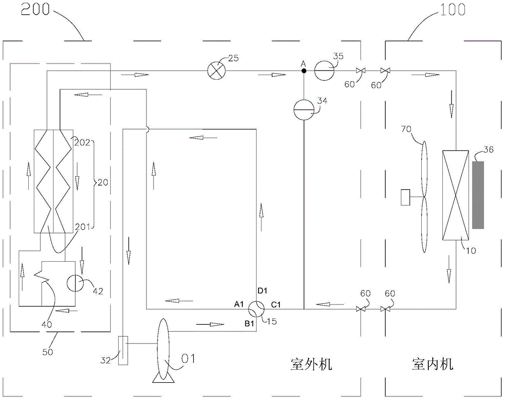
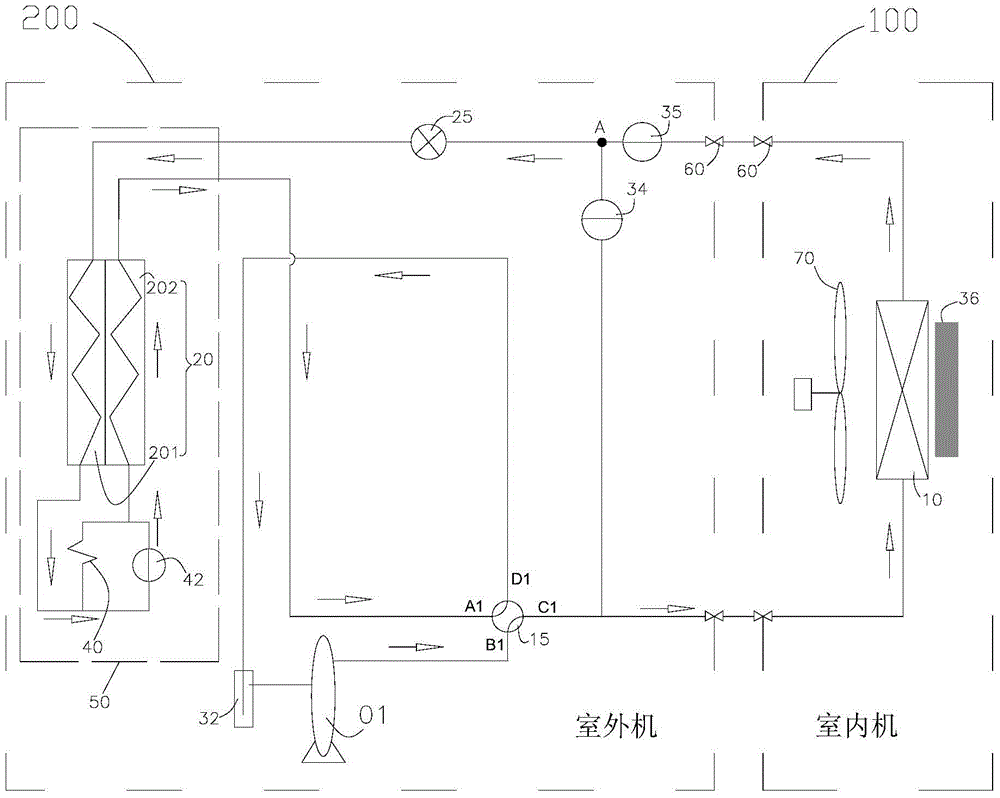
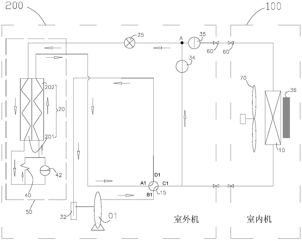
[0032] refer to Figure 1 to Figure 3 , an embodiment of the air conditioning system of the present invention includes an indoor unit 100 and an outdoor unit 200, the indoor unit 100 includes an indoor heat exchanger 10, and the outdoor unit 200 includes a compressor 01, a four-way valve 15, an outdoor heat exchanger assembly 50 and a throttling Component 25, outdoor heat exchanger assembly 50 includes outdoor heat exchanger 20; compressor 01, four-way valve 15, indoor heat exchanger 10, throttling element 25, and outdoor heat exchanger 20 are sequentially connected to ...


PUM


Abstract

The present invention provides an air-conditioning system, which includes a compressor, a four-way valve, an indoor heat exchanger, a throttling element, an outdoor heat exchanger assembly, a first solenoid valve and a second solenoid valve connected in sequence, and the outdoor heat exchanger assembly includes Outdoor heat exchanger; the second solenoid valve is connected in series between the indoor heat exchanger and the throttling element, the indoor heat exchanger after series connection, the second solenoid valve and the first solenoid valve are connected in parallel, or the indoor heat exchanger after series connection, The second solenoid valve and the throttling element are connected in parallel with the first solenoid valve; the four-way valve has first to fourth valve ports, the first valve port is connected to the first port of the outdoor heat exchanger, and the second port of the outdoor heat exchanger is connected to The throttling element, the second valve port is connected to the exhaust end of the compressor, the third valve port is respectively connected to the first port of the indoor heat exchanger and the first solenoid valve, and the second port of the indoor heat exchanger is connected to the second solenoid valve, The fourth valve port communicates with the suction end of the compressor. The air conditioning system of the present invention enables the heat pump air conditioner to quickly defrost the outdoor heat exchanger.

Description

technical field [0001] The invention relates to the refrigeration field, in particular to an air conditioning system. Background technique [0002] In the continuous heating cycle mode, the existing air-conditioning system often achieves the purpose of continuous heating through the heat absorbed and released by the heat storage material, but the use of heat storage to achieve continuous defrosting has the following possible hidden dangers: 1) Insufficient heat storage of the heat storage material leads to lack of heat in the process of continuous heating and defrosting, which causes the return air of the compressor to carry liquid and wear the compressor; The temperature effect is not ideal. During this period of defrosting cycle, half of the time the difference between the outlet air temperature and the inlet air temperature is not large, no heat is blown out, and the heating effect is poor during defrosting; 3) The heat storage form requires redesigning the storage The t...

Claims


Application Information

Patent Timeline
Patent Type & Authority Patents(China)
IPC IPC(8): F25B13/00F25B29/00F25B47/02F25B41/04F25B41/06F25B41/20F25B41/24F25B41/30
CPCF24F5/001F24F11/30F24F11/83F24F11/41F24F11/84
Inventor 韩雷周中华郭瑞安李俊峰陈军宇刘冰军
Owner GREE ELECTRIC APPLIANCES INC
Why Eureka
Try Eureka