Robot hand-eye stereo vision measurement method

A technology of stereo vision measurement and robotics, applied in the direction of measuring devices, photogrammetry/video metrology, instruments, etc., can solve the problems of not being able to obtain depth or height information, and can not meet the requirements, and achieve strong practicability and reliability, and widely Application field, the effect of huge application value

Inactive Publication Date: 2015-04-15
SHENYANG SIASUN ROBOT & AUTOMATION
View PDF5 Cites 11 Cited by
  • Summary
  • Abstract
  • Description
  • Claims
  • Application Information

AI Technical Summary

Problems solved by technology

Its shortcoming is that only the two-dimensional information of the workpiece can be obtained, and its depth or height information cannot be obtained
Unable to meet the higher requirements of industrial robot assembly, palletizing and other tasks

Method used


Image

  • Robot hand-eye stereo vision measurement method
  • Robot hand-eye stereo vision measurement method
  • Robot hand-eye stereo vision measurement method

Examples


Embodiment Construction

[0021] In order to make the object, technical solution and advantages of the present invention clearer, the present invention will be described in further detail below in conjunction with specific embodiments and with reference to the accompanying drawings.

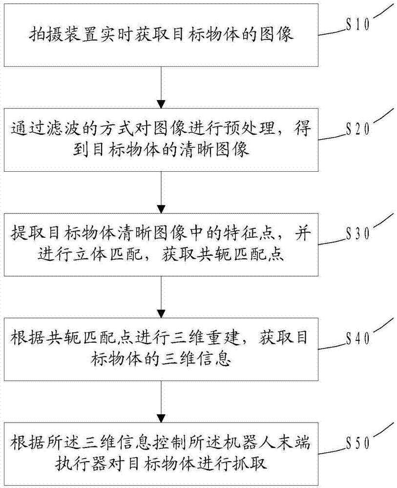
[0022] Please refer to figure 1 A method for measuring robot hand-eye stereo vision, comprising a photographing device and a robot, the method comprising the steps of:

[0023] S10: The photographing device acquires an image of the target object in real time.

[0024] The photographing device is fixed on the end effector of the robot arm and moves together with the end effector, so that the photographing device acquires images of the same target object at multiple different positions (two in this embodiment). In , two images are acquired. In this embodiment, the photographing device is a video camera.

[0025] Before the photographing device acquires an image, the photographing device must be calibrated first, and the ...


PUM


Abstract

The invention relates to a robot hand-eye stereo vision measurement method. A target scene is shot from two different directions through an industrial camera installed on an industrial robot end effector. After camera calibration and image preprocessing, conjugate matching points of the two images are searched, and finally three-dimensional reconstruction is carried out according to the conjugate matching points so as to obtain the three-dimensional coordinate of a workpiece surface point. Compared with the currently common stationary industrial robot hand-eye vision measurement, the method provided by the invention can acquire the three-dimensional information of the workpiece rather than a simple two-dimensional coordinate of the workpiece, greatly expands the application of the vision system in industrial robot assembly, sorting and other systems, and has enormous application value and broad application field.

Description

technical field [0001] The invention relates to the field of robot vision measurement, in particular to a method for measuring robot hand-eye stereo vision. Background technique [0002] In the traditional robot production line, the vast majority of industrial robots that perform grabbing and handling tasks work by precise teaching or offline programming. The initial pose and end pose of the target object are strictly limited, and the robot can only complete point-to-point work. However, in many cases, especially the assembly line, the workpiece pose is often not fixed. There is always a deviation between the actual target object and the ideal target object pose. Even if this deviation is small, it will lead to the failure of the robot operation task. This situation that the robot cannot complete the task well due to the change of the environment greatly limits the practical application range of the robot. With the advancement of modern manufacturing technology, the requir...

Claims


Application Information

Patent Timeline
Patent Type & Authority Applications(China)
IPC IPC(8): G01C11/00
CPCG01C11/00
Inventor 徐方曲道奎邹风山王帅李邦宇褚明杰
Owner SHENYANG SIASUN ROBOT & AUTOMATION
Why Eureka
Try Eureka