Moving parking facility

A kind of parking equipment, mobile technology, applied in the field of mobile parking equipment, can solve the problems such as unable to remove foreign matter, achieve the effect of suppressing manufacturing cost and suppressing the increase of manufacturing cost

Active Publication Date: 2015-04-15
IHI CORP
View PDF11 Cites 12 Cited by
  • Summary
  • Abstract
  • Description
  • Claims
  • Application Information

AI Technical Summary

Problems solved by technology

[0008] However, in the above-mentioned prior art, the intrusion of foreign matter between the power receiving unit and the power feeding unit is...

Method used


Image

  • Moving parking facility
  • Moving parking facility
  • Moving parking facility

Examples


no. 1 Embodiment approach

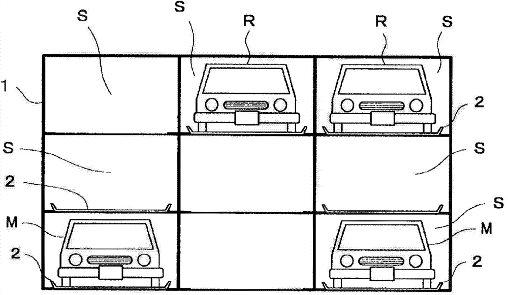
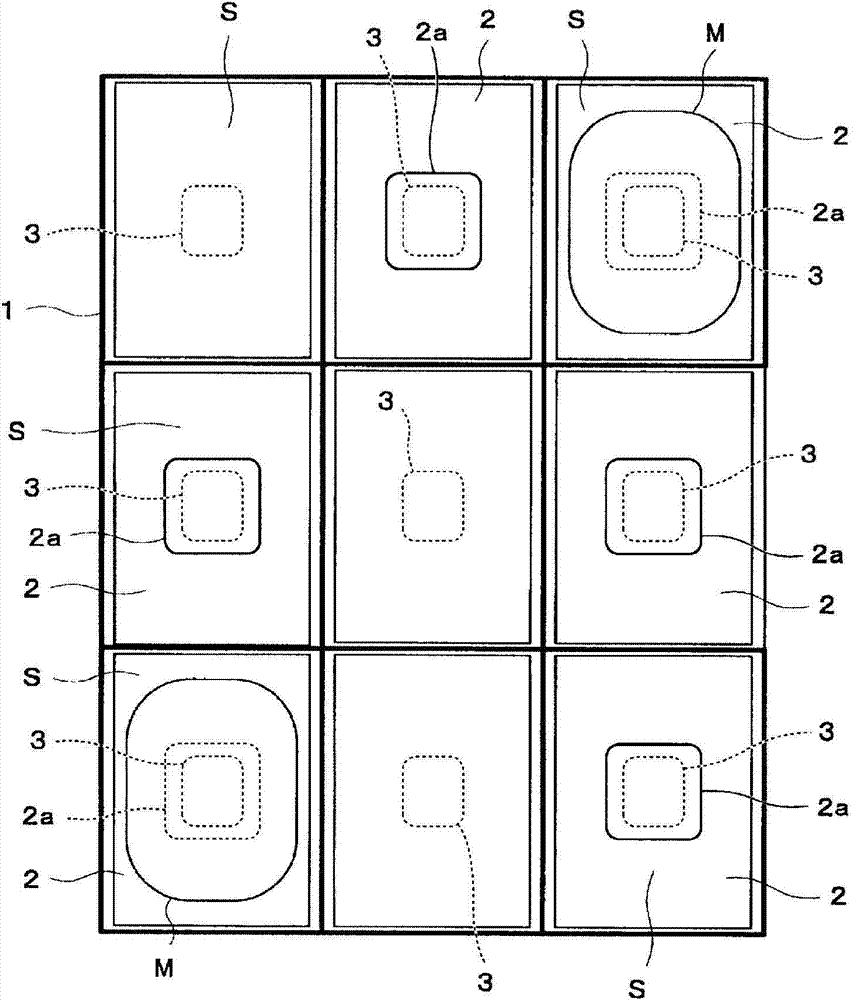
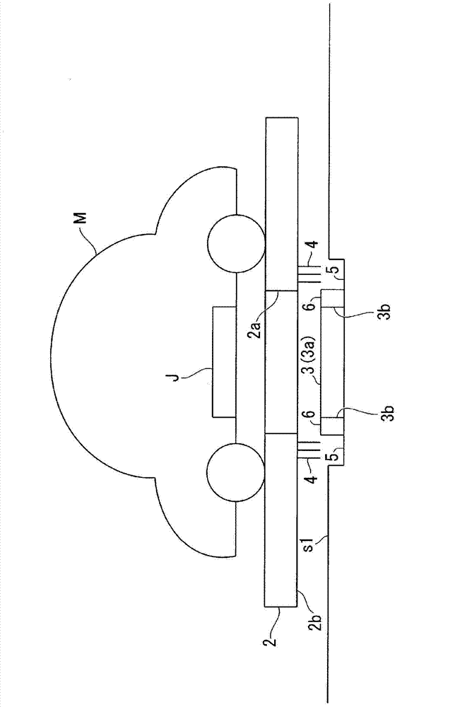
[0033] First, the first embodiment will be described. Such as Figure 1A , Figure 1B as well as figure 2 As shown, the mechanical parking lot (mobile parking facility) of the first embodiment is composed of a vehicle storage rack 1 , a pallet 2 , a power supply coil 3 , a foreign object removal unit 4 , a foreign object storage unit 5 and a foreign object access prevention unit 6 .

[0034] Such as Figure 1A as well as Figure 1B As shown, the vehicle storage rack 1 includes a plurality of (total 27) storage spaces S arranged in front, rear, left, right, and up and down, respectively. For the convenience of description, the vehicle storage rack 1 shown in these figures defines a storage space S, but in practice, more or less storage spaces S may also be provided. exist Figure 1A , 1B Among them, the storage spaces S are three rectangular areas arranged in the front-back direction, the left-right direction, and the up-down direction, and a part of them accommodates the ...

no. 2 Embodiment approach

[0050] Next, a mechanical parking lot according to the second embodiment will be described.

[0051] Such as Figure 5 as well as Figure 6 As shown, the mechanical parking lot according to the second embodiment is further provided with a first foreign matter entry prevention wall 7 and a second foreign matter entry prevention wall 8 in addition to the first embodiment. Other components are the same as those of the first embodiment. Therefore, in the second embodiment, descriptions of the same components as those in the first embodiment are omitted. also, Figure 6 In the diagram, the positional relationship between the opening 2a, the second foreign matter entry prevention wall 8, the foreign matter removal part 4, the power supply coil 3, the foreign matter access prevention part 6, the foreign matter storage part 5, and the first foreign matter entry prevention wall 7 is simplified for easy reading. means, in fact Figure 5 positional relationship as shown.

[0052] T...


PUM


Abstract

This moving parking facility is provided with: a pallet (2) which has a moving vehicle (M) placed thereon, which is moved horizontally to accommodate the moving vehicle (M) in an accommodation space, and which has a magnetic-field-transmitting region corresponding to a power-receiving coil (J) provided to a bottom surface of the moving vehicle (M); a power-supplying coil (3) which is provided to the accommodation space so as to be facing the magnetic-field-transmitting region, and which contactlessly supplies power to the power-receiving coil (J); and a foreign-substance removal unit (4) which is provided to a lower surface (2b) of the pallet (2), and which, in a state of being in contact with or separated by a constant space from an upper surface (3a) of the power-supplying coil (3), engages with foreign substances as the pallet (2) is moved, thereby removing foreign substances present on the upper surface (3a) of the power-supplying coil (3).

Description

technical field [0001] The present invention relates to mobile parking equipment. [0002] this application claims priority from Japanese Patent Application No. 2012-180551 for which it applied in Japan on August 16, 2012, and uses the content here. Background technique [0003] Patent Document 1 below discloses a contactless power feeding system capable of safely and efficiently feeding power without foreign matter entering the space between a power receiving unit provided on the bottom surface of a vehicle and a power feeding unit buried in a parking space. In the above-mentioned non-contact power supply system, an insulating spacer is provided in the space between the power receiving unit of the vehicle and the power supply unit of the parking space, and the spacer is stored in the floor by the movable part during times other than power supply. On the other hand, when power is supplied, the spacer is moved by the movable part to the space between the power receiving part...

Claims


Application Information

Patent Timeline
IPC IPC(8): H02J17/00B60M7/00E04H6/42H02J7/00B60L11/18
CPCY02T90/125B60L11/182Y02T90/14Y02T90/121Y02T90/163B60L11/1825Y02T10/7005E04H6/22B60L2270/147B60L11/1829E04H6/34H02J17/00Y02T90/122Y02T10/7088B60L2230/16Y02T90/128B60L53/12B60L53/31B60L53/38E04H6/42B60L53/305H02J50/10H02J50/12H02J50/60H02J50/90B60L53/124B60L53/122Y02T10/7072Y02T90/12Y02T90/16Y02T10/70H02J50/40H02J50/80
Inventor 新妻素直
Owner IHI CORP
Why Eureka
Try Eureka