Sleeve type general expansion mold for precise expanding

A sleeve-type, precise technology, applied in the field of sleeve-type precision expanding general-purpose expansion molds, can solve problems such as high cost and complex structure, and achieve the effect of guaranteed strength, guaranteed accuracy, and convenient removal

Inactive Publication Date: 2015-04-22
SICHUAN NINGJIANG SHANCHUAN MACHINERY
View PDF6 Cites 7 Cited by
  • Summary
  • Abstract
  • Description
  • Claims
  • Application Information

AI Technical Summary

Problems solved by technology

[0003] The purpose of the present invention is to overcome the deficiencies of the current technology, to provide a sleeve-like precision expanding general-purpose expansion mold, and to solve the defects of complex structure and high cost of the existing expansion mold.

Method used


Image

  • Sleeve type general expansion mold for precise expanding
  • Sleeve type general expansion mold for precise expanding
  • Sleeve type general expansion mold for precise expanding

Examples


Embodiment 1

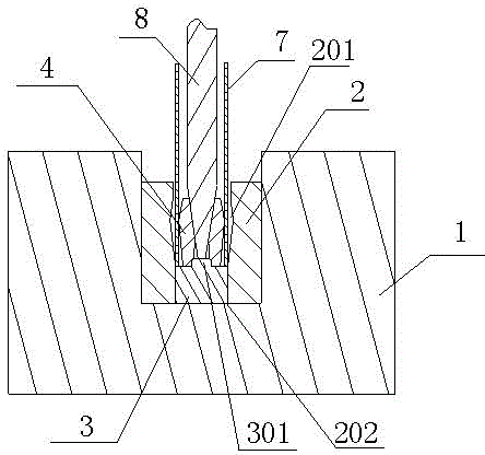
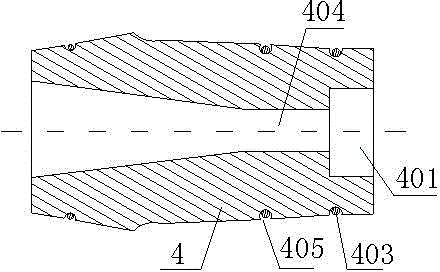
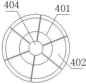
[0025] like Figure 1-3 As shown, the sleeve-type precision expanding general-purpose expansion mold includes a mold base 1, a concave mold 2, a positioning column 3 and an elastic combination module 4. The concave mold 2 is in the shape of a sleeve, and the concave mold 2 is vertically arranged on the On the mold base 1, one end of the barrel mouth 201 is directly facing the mold base 1 below, the positioning column 3 and the elastic combination module 4 are located in the through groove 202 of the die 2, the lower end of the positioning column 3 is installed on the mold base 1, and the upper end is provided with a The round table 301, the elastic combination module 4 is a rotary body, the center lines of the die 2, the positioning column 3 and the elastic combination module 4 overlap, and the center of the lower end of the elastic combination module 4 is provided with a groove 401 that matches the round platform 301, and the elastic combination The module 4 is evenly divided...

Embodiment 2

[0029] like Figure 4, the structure of this embodiment is basically the same as that of Embodiment 1, the difference is that a discharge device 5 is provided below the mold base 1, and the discharge device 5 includes a push rod 501, a push rod 502, and a push rod 503 , a push plate 507, and an upper backing plate 504, a pad cover A505, and a lower backing plate 506 arranged from top to bottom between the die 2 and the mold base 1, and the end of the ejector rod 501 is provided with A circular plate 508, the circular plate 508 is located in the sleeve hole of the cushion cover A505, the ejector rod 501 is located on the lower end surface of the circular plate 508, and passes through the lower backing plate 508, the mold base 1 is connected to the outside, and one end of the push rod 502 is fixed on the circular plate 508 The upper end surface, the other end passes through the upper backing plate 504 and the positioning column 3, and when the circular plate 508 is located at th...

Embodiment 3

[0033] like Figure 5 , the structure of this embodiment is basically the same as that of Embodiment 2, the difference is that the die 2 is fixed on the mold base 1 through a fixing device 6, and the fixing device 6 includes a compression sleeve 601 and a die fixing sleeve 604 , the die fixing sleeve 604 wraps the die 2, the die fixing sleeve 604 is located in the installation groove 101 on the upper surface of the mold base 1, the compression sleeve 601 is located above the die fixing sleeve 604, and the die fixing sleeve 604 is sealed in the installation In the groove 101 , the compression sleeve 601 is fixed on the mold base 1 , and the compression sleeve 601 is provided with a through hole facing the through groove 202 .


PUM


Abstract

The invention discloses a sleeve type general expansion mold for precise expanding. The mold comprises a mold base (1), a concave mold (2), a positioning column (3) and an elastic combination module (4), wherein the concave mold (2) takes the shape of a sleeve, and is vertically arranged on the mold base (1); the positioning column (3) and the elastic combination module (4) are positioned in a through groove (202) of the concave mold (2); the lower end of the positioning column (3) is mounted on the mold base (1), and the upper end is provided with a circular table (301); the elastic combination module (4) is a rotating body; and center lines of the concave mold (2), the positioning column (3) and the elastic combination module (4) are overlapped. The mold has the following beneficial effects: the device uses multiple piece blocks which are same in size and restrained by springs, and the piece blocks are spliced as a seamlessly bonded whole at ordinary times; and after a pressure rod penetrates through a through hole of the whole to collapse the piece blocks, a workpiece wrapped at the periphery is expanded.

Description

technical field [0001] The invention relates to an expansion mold, in particular to a universal expansion mold with precise diameter expansion of sleeves. Background technique [0002] Precision expansion of sleeve parts has always been a difficult point in the mold design process. In foreign countries, special equipment is used to complete it, and the cost is quite high. Domestic manufacturers are exploring the use of general equipment to achieve expansion. The mold structure is rubber ( Polyurethane) punch, "clip" type punch and "liquid" type punch; rubber (polyurethane) punch is used, because the expansion force of sleeve parts is large when the diameter is expanded, the rubber (polyurethane) punch cannot achieve If the strength is large enough, the dimensional accuracy cannot be achieved due to insufficient expansion force; while using the "circlip" type punch, although a large expansion force can be achieved, the mold structure is more complicated, and the mold strength...

Claims


Application Information

Patent Timeline
Patent Type & Authority Applications(China)
IPC IPC(8): B21D37/10B21D39/08
CPCB21D37/10B21D39/08
Inventor 杨君涛
Owner SICHUAN NINGJIANG SHANCHUAN MACHINERY
Why Eureka
Try Eureka