Rapid heating and forming integrated device and method

A technology for rapid heating and forming of parts, applied in the field of industrial manufacturing, can solve the problems of difficult temperature field control, long process, complicated operation, etc., and achieve the effect of solving one-step forming, scientific and reasonable design, and convenient use.

Active Publication Date: 2015-04-22
HARBIN INST OF TECH AT WEIHAI
View PDF6 Cites 12 Cited by
  • Summary
  • Abstract
  • Description
  • Claims
  • Application Information

AI Technical Summary

Problems solved by technology

In practical applications, in order to further improve the performance of components, heat treatment is required after forming; however, heat treatment after forming has a series of problems: it will destroy the shape of the part, the process is long at the same time, the production method is cumbersome, and the energy consumption is increased.
Some scholars have proposed to directly heat the billet to the heat treatment temperature in the heating furnace, and then quickly shape it and cool it in the mold to achieve the purpose of heat treatment; however, the heating in the furnace belongs to the overall heating, and it is impossible to realize the variable temperature heating of different regions of the part.
Some scholars have proposed a dual-electrode resistance heating method, but the dual-electrode is only suitable for simple-shaped billets, and it is extremely difficult to control the temperature field for complex shapes, and the device used is complex in structure and cumbersome in operation.

Method used


Image

  • Rapid heating and forming integrated device and method

Examples


Embodiment Construction

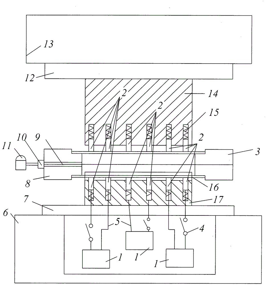
[0025] The present invention will be further described in detail below in conjunction with the accompanying drawings and specific embodiments.

[0026] Such as figure 1 The present invention shown includes power supply 1, electrode 2, right sealing punch 3, power switch 4, wire 5, base 6, workbench 7, left sealing punch 8, medium channel 9, medium filling power switch 10, high power supply 11 , slider 12, upper beam 13, upper mold 14, elastic device 15 and lower mold 17.

[0027] The power supply 1 is three or more. Upper mold 14 corresponds to lower mold 17. A slide block 12 is fixed under the upper beam 13 ; an upper mold 14 is fixed under the slide block 12 . The lower mold 17 is fixed on the workbench 7 on the base 6 . A left sealing punch 8 is arranged on the left side between the upper die 14 and the lower die 17, and a right sealing punch 3 is arranged on the right side. There is a medium channel 9 on the left sealing punch 8; a medium filling power switch 10 is ar...


PUM


Abstract

The invention discloses a rapid heating and forming integrated device which comprises power sources, an upper die and a lower die and further comprises an upper beam and electrodes. The multiple power sources are arranged. The upper die corresponds to the lower die. A sliding block is fixed to the lower face of the upper beam. The upper die is fixed to the lower face of the sliding block. The lower die is fixed to the upper face of a work table located on a base. A left sealing punch is arranged on the left side of the portion between the upper die and the lower die and a right sealing punch is arranged on the right side of the portion between the upper die and the lower die. A medium channel is formed in the left sealing punch. A medium filling power switch is arranged at the portion, corresponding to the medium channel, on the outer side face of the left sealing punch. The medium channel is connected with a high voltage source through the medium filling power switch. A use method includes ten steps. The device is simple in structure, more scientific and reasonable in design and convenient to use; a blank is rapidly heated in a suspended mode, the low-temperature state of the dies is guaranteed, and a cold die is directly used for conducting thermal treatment in the forming process; meanwhile, different regions are heated at variable temperatures through the multiple electrodes, so that a variable-performance part is formed at a step.

Description

technical field [0001] The invention relates to an integrated device and method, in particular to a rapid heating and forming integrated device and method, belonging to the technical field of industrial manufacturing. Background technique [0002] Due to the high flexural modulus and shear modulus of hollow section members, it is considered to be the best structural form to achieve lightweight structures, and is widely used in aviation, aerospace, automobiles and bicycles and other industries. In practical applications, in order to further improve the performance of components, heat treatment is required after forming; however, heat treatment after forming has a series of problems: it will destroy the shape of the part, the process is long, the production method is cumbersome, and the energy consumption is increased. Some scholars have proposed to directly heat the billet to the heat treatment temperature in the heating furnace, and then quickly shape it and cool it in the m...

Claims


Application Information

Patent Timeline
Patent Type & Authority Applications(China)
IPC IPC(8): B21D37/10B21D37/16
CPCB21D37/10B21D37/16
Inventor 初冠南赵洪运姚圣杰
Owner HARBIN INST OF TECH AT WEIHAI
Why Eureka
Try Eureka