Cleaning and cooling device for silicon wafer before printing in solar battery cell preparation process

A technology of solar cell and preparation process, applied in sustainable manufacturing/processing, circuits, photovoltaic power generation, etc., can solve the problems of easy residual foreign matter and poor cleaning effect on silicon wafers, and achieves favorable heat dissipation and reduces punctured damage. Probability, the effect of large contact area

CN106784168AActive Publication Date: 2017-05-31EGING PHOTOVOLTAIC TECHNOLOGY CO LTD
5 Cites 2 Cited by

Patent Information

Authority / Receiving Office
CN · China
Patent Type
Applications(China)
Current Assignee / Owner
Publication Date
2017-05-31

Smart Images

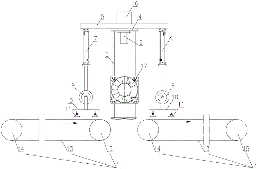
  • Figure 1
    Figure 1
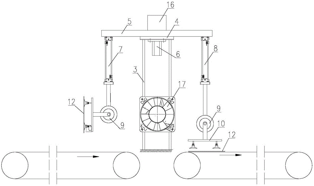
  • Figure 2
    Figure 2
Patent Text Reader

Abstract

The invention relates to the technical field of preparation of solar battery cells and in particular relates to a cleaning and cooling device for a silicon wafer before printing in a solar battery cell preparation process. The cleaning and cooling device comprises a first belt conveying device and a second belt conveying device; a bracket is arranged between the first belt conveying device and the second belt conveying device; a platform is arranged at the top of the bracket; the platform is rotatably connected with a rotary table; a motor is fixed on the lower surface of the platform; a first air cylinder and a second air cylinder are symmetrically arranged on the lower surface of the rotary table; rotary air cylinders are fixed at stretching-out ends of the first air cylinder and the second air cylinder; supporting rods are fixed at output ends of the rotary air cylinders; a plurality of suction discs are fixed on lower surfaces of the supporting rods; a fan is fixed at the side of the bracket. According to the cleaning and cooling device provided by the invention, the conveying efficiency of the silicon wafer is not hindered and impurities on the surface of the silicon wafer are completely removed; the probability that a screen printing plate is punctured is reduced and the temperature on the surface of the silicon wafer can be greatly reduced, so that the volatilization speed of organic matters of slurry in the screen printing plate is reduced and a relatively good printing performance can be kept.
Need to check novelty before this filing date? Find Prior Art

Description

technical field

[0001] The invention relates to the technical field of solar cell preparation, in particular to a cleaning and cooling device for silicon wafers before printing in the solar cell preparation process. Background technique

[0002] The preparation process of crystalline silicon solar cells mainly includes: cleaning, removing damaged layer, texturing, diffusion, junction making, etching, deposition of anti-reflection film, printing, sintering, and cell test. Among them, printing is an important process in the production process of crystalline silicon solar cells. When the silicon wafer is transported to the printing process in the previous process of printing, the temperature of the silicon wafer itself is high and foreign matter is easy to adhere to the surface. On the one hand, if the surface of the silicon wafer has Impurities are easy to puncture the screen or crack the silicon wafer, and the service life of the screen will have a great impact on the product...

Examples

Embodiment 1

[0016] Such as figure 1 and 2 As shown, a device for cleaning and cooling silicon wafers before printing in the solar cell production process includes a first belt conveyor 1 and a second belt conveyor 2, and the first belt conveyor 1 and the second belt conveyor 2 are arranged between There is a bracket 3, a platform 4 is arranged on the top of the bracket 3, a turntable 5 is rotatably connected to the platform 4, a motor 6 is fixed on the lower surface of the platform 4, the output end of the motor 6 is fixedly connected with the turntable 5, and the lower surface of the turntable 5 is arranged symmetrically There are a first cylinder 7 and a second cylinder 8, the extending ends of the first cylinder 7 and the second cylinder 8 face downward, and the extending ends of the first cylinder 7 and the second cylinder 8 are fixed with a rotary cylinder 9, and the rotary cylinder 9 is fixed with pole 10 on the output end, and the lower surface of pole 10 is fixed with some sucker...