Push rod mechanism of metal die-casting mold

A push rod mechanism and die-casting die technology, applied in the field of metal die-casting, can solve the problems of sticking together, unable to achieve rapid push-out, etc., and achieve the effects of easy processing and maintenance, safe and reliable push-out action, and improved service life.

Inactive Publication Date: 2015-04-22
HEFEI MAILI NETWORK TECH
View PDF0 Cites 0 Cited by
  • Summary
  • Abstract
  • Description
  • Claims
  • Application Information

AI Technical Summary

Problems solved by technology

But at present, when the push rod is pushing out the die casting, because the contact between the die casting and the push rod is in plane contact, if the die casting is completely cooled, the top of the push rod and the bottom of the die casting will be bonded together due to pressure , cannot achieve fast rollout

Method used


Image

  • Push rod mechanism of metal die-casting mold

Examples


Embodiment Construction

[0013] In order to make the object, technical solution and advantages of the present invention clearer, the present invention will be further described in detail below in conjunction with the accompanying drawings and embodiments. It should be understood that the specific embodiments described here are only used to explain the present invention, not to limit the present invention.

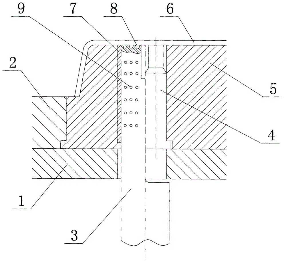
[0014] see figure 1 , figure 1 It is a structural schematic diagram of the present invention.

[0015] The push rod mechanism of a metal die-casting mold includes a support plate 1, a movable template 2, a push rod 3, and a die casting 6. The movable template 2 is installed above the support plate 1, and between the support plate 1 and the movable template 2 A concentric installation hole is opened on the top, the push rod 3 passes through the installation hole and contacts the bottom end of the die casting 6, one side of the push rod 3 is connected with the plastic guide sleeve layer 7, and the ...


PUM


Abstract

The invention relates to a push rod mechanism of a metal die-casting mold. The push rod mechanism comprises a supporting plate, a movable mold plate, a push rod and a die-casting part. The movable mold plate is installed on the supporting plate. Concentric installation holes are formed in the supporting plate and the movable mold plate. The push rod penetrates through the installation holes and makes contact with the bottom end of the die-casting part. One side of the push rod is connected with a plastic guide sleeve layer, and the other side of the push rod is connected with a formed insert. The formed insert is embedded into a main core. The plane, making contact with the die-casting part, of the push rod is provided with a plurality of trapezoid-shaped slots downwards, and a plurality of radiating holes are formed in the outer cylindrical face of the push rod. According to the push rod mechanism, the structure is simple, machining and maintenance are convenient, the push-out actions are safe and reliable, and running faults are not likely to occur; due to the fact that the trapezoid-shaped slots are formed in the upper surface of the push rod, gas at the contact position is effectively exhausted, and the phenomenon that the top end of the push rod and the bottom end of the die-casting part are adhesively connected together due to the pressure effect and cannot achieve rapid outward pushing is avoided; meanwhile, the radiating holes are formed, so that the service life of the push rod is prolonged, and the lubricating effect of the push rod is improved.

Description

technical field [0001] The invention relates to the field of metal die-casting, in particular to a push rod mechanism of a metal die-casting mold. Background technique [0002] Metal die-casting is the process of filling molten metal into the cavity of a die-casting model at a high speed under high pressure, and solidifying the molten metal under high pressure to form a metal die-casting. One of the most efficient. With the development of metal die-casting, metal die-casting technology, plastic injection molding, and metal plate stamping are listed as three major molding systems. The salient features of metal die-casting are: it can form non-ferrous metal structural parts with complex shapes and thin walls. It is a high-efficiency, high-precision, high-interchangeability, and low-consumption precision parts forming technology. Die-casting is realized by running. [0003] After the molten metal is cooled and solidified in the mold cavity, due to molding shrinkage and other...

Claims


Application Information

Patent Timeline
Patent Type & Authority Applications(China)
IPC IPC(8): B22D17/22
CPCB22D17/2236
Inventor 王宁
Owner HEFEI MAILI NETWORK TECH
Why Eureka
Try Eureka