
Stencil clamping sizing device and sizing method thereof

A clamping device and clamping technology, applied in the field of plate making and printing, can solve the problems of affecting the yield and quality of stencil making, unable to achieve the uniformity of sizing, and the effect of the operator's sizing effect, so as to avoid the problem of manual sizing. Uniform, easy sizing, high bond strength

Active Publication Date: 2015-04-22
CHENGDU BANKNOTE PRINTING
View PDF7 Cites 6 Cited by
  • Summary
  • Abstract
  • Description
  • Claims
  • Application Information

AI Technical Summary

Problems solved by technology

However, the existing sizing methods are all manually sizing the gap between the plate cylinder and the end ring, which cannot meet the requirements of sizing uniformity, and because the sizing position is inconvenient, the operator’s sizing effect is caused. Influence, thus greatly affecting the yield and quality of the stencil production, reducing the printing durability of the stencil

Method used


Image

  • Stencil clamping sizing device and sizing method thereof
  • Stencil clamping sizing device and sizing method thereof
  • Stencil clamping sizing device and sizing method thereof

Examples


Embodiment Construction

[0024] Below in conjunction with accompanying drawing, the present invention is described in detail.

[0025] In order to make the object, technical solution and advantages of the present invention clearer, the present invention will be further described in detail below in conjunction with the accompanying drawings and embodiments. It should be understood that the specific embodiments described here are only used to explain the present invention, not to limit the present invention.

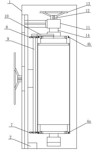
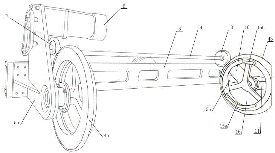
[0026] Such as figure 2 and 3 As shown, a stencil clamping and sizing device includes a sizing cabinet 1, a stencil clamping device and a timing heater 2 arranged in the sizing cabinet 1, and the stencil clamping device includes a rotating mount 3, a clamping Ring composition and clamping ring rotation drive mechanism, the rotation mount 3 is connected to the rotation drive mechanism of the rotation mount, the rotation drive mechanism of the rotation mount includes a shaft fixedly connected wit...


PUM


Abstract

The invention discloses a stencil clamping sizing device. The stencil clamping sizing device comprises a sizing cabinet, a stencil clamping unit and a timing heater. The stencil clamping unit comprises a rotating mounting base, a clamping ring assembly and a clamping ring rotation drive mechanism, wherein the rotating mounting base is connected to a rotating mounting base rotation drive mechanism, the clamping ring assembly is composed of a fixed clamping ring and a movable clamping ring which are rotatably connected to a fixed clamping ring mounting base and a movable clamping ring mounting base through rolling bearings respectively, and the clamping ring drive mechanism is used for driving the fixed clamping ring and the movable clamping ring to rotate to the same direction synchronously. A movable clamping ring adjustment mechanism is mounted on the movable clamping ring mounting base. The stencil clamping sizing device uses automatic uniform sizing and sealing heating drying by clamping a money printing stencil, so that an end ring and a stencil cylinder are high in adhesive strength, the deficiency that manual sizing is uneven, low in yield and print run and the like, and the print run rate of the stencil is greatly increased in a printing production process of the stencil.

Description

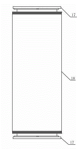
technical field [0001] The invention belongs to the technical field of printing and plate making, and in particular relates to a stencil clamping and sizing device and a sizing method thereof. Background technique [0002] In the existing stencil printing technology, most of the screen printing methods are screen printing holes formed by weaving. The printing method is mainly planar printing, and the stretching method is also mostly used. In the field of stencil printing, high-speed printing is mostly rotary printing, and the banknote plates required for rotary stencil printing need to be clamped into a cylinder before printing. [0003] Such as figure 1 As shown, the existing stencil is mainly composed of a plate cylinder 18 and an end ring 17 arranged at both ends of the plate cylinder 18. Among them, whether a 70-80um stencil is suitable for mass production printing mainly depends on the strength of the stencil itself and the bonding strength between the stencil and the...

Claims


Application Information

Patent Timeline
Patent Type & Authority Applications(China)
IPC IPC(8): B41F27/14
Inventor 曹娅姚俊任红卫郭春莲
Owner CHENGDU BANKNOTE PRINTING
Learn More