Device for adjusting camber angle of rear wheel of automobile

A technology of adjusting device and camber angle, applied in vehicle parts, transportation and packaging, steering mechanism, etc., can solve problems such as affecting the accurate positioning of the car, easy shaking of eccentric bolts, etc., to avoid slippage, avoid deflection, and reduce frequency. and cost effects

Active Publication Date: 2017-07-11
CHERY AUTOMOBILE CO LTD
View PDF7 Cites 0 Cited by
  • Summary
  • Abstract
  • Description
  • Claims
  • Application Information

AI Technical Summary

Problems solved by technology

[0006] In order to solve the problem that the eccentric bolts in the prior art are easy to shake and affect the accurate positioning of the car, the embodiment of the present invention provides a camber adjustment device for the rear wheel of the car

Method used


Image

  • Device for adjusting camber angle of rear wheel of automobile
  • Device for adjusting camber angle of rear wheel of automobile
  • Device for adjusting camber angle of rear wheel of automobile

Examples


Embodiment 1

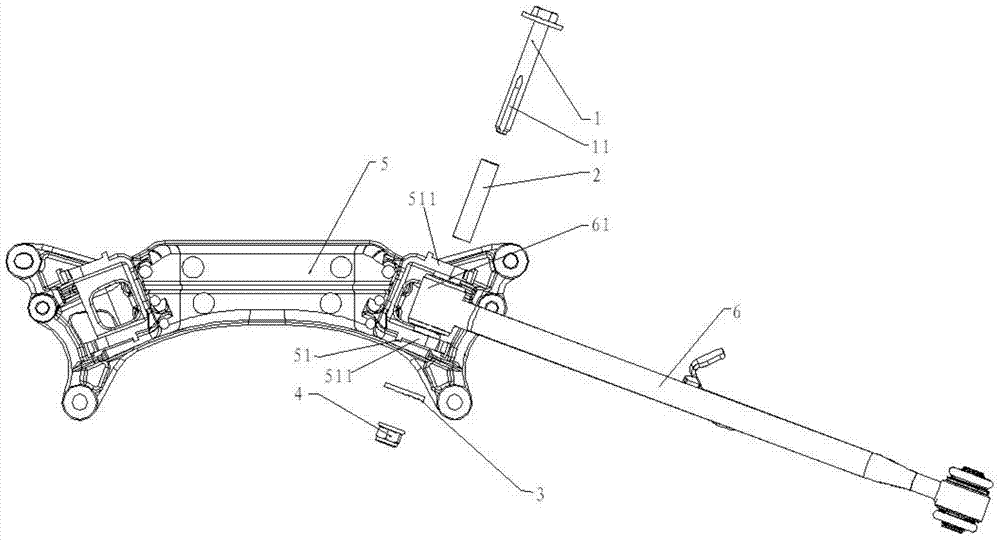
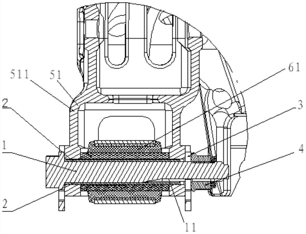
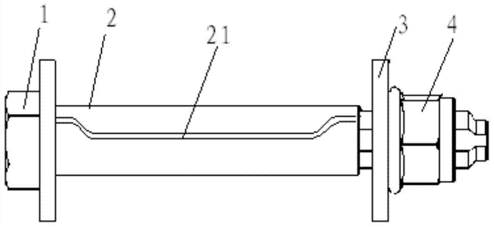
[0031] Such as figure 1 shown, see also figure 2 and image 3 , the embodiment of the present invention provides an automobile rear wheel camber adjustment device, said automobile rear wheel camber adjustment device comprising: eccentric bolt 1, elastic sleeve 2, eccentric washer 3 and lock nut 4, said eccentric The bolts 1 are sequentially passed through the two legs 511 of the lower swing arm mounting bracket 51, and the eccentric bolts 1 are also passed through the lower swing arm mounting head 61 between the two legs 511. The sleeve 2 is set on the eccentric bolt 1, and the elastic sleeve 2 is located between the eccentric bolt 1 and each of the legs 511, between the eccentric bolt 1 and the installation head 61 of the lower swing arm. Between, the eccentric washer 3 and the lock nut 4 are both sleeved on the eccentric bolt 1, and the lock nut 4 is located outside the leg 511 near the tail of the eccentric bolt 1, so The eccentric washer 3 is arranged between the locki...

Embodiment 2

[0036] Such as figure 1 shown, see also figure 2 and image 3Another embodiment of the present invention provides a rear wheel camber adjustment device for an automobile, which includes: an eccentric bolt 1, an elastic sleeve 2, an eccentric washer 3 and a lock nut 4, the The eccentric bolts 1 are sequentially threaded on the two legs 511 of the lower arm mounting bracket 51, and the eccentric bolts 1 are also threaded in the lower arm mounting head 61 between the two legs 511, so that The elastic sleeve 2 is sleeved on the eccentric bolt 1, and the elastic sleeve 2 is located between the eccentric bolt 1 and each of the legs 511, the eccentric bolt 1 and the installation head of the lower swing arm 61, the eccentric washer 3 and the lock nut 4 are set on the eccentric bolt 1, and the lock nut 4 is located outside the leg 511 near the tail of the eccentric bolt 1 , the eccentric washer 3 is arranged between the locking nut 4 and the leg 511 , and the elastic sleeve 2 is pr...


PUM


Abstract

The invention discloses an automobile rear wheel camber adjustment device, which comprises: an eccentric bolt, an elastic sleeve, an eccentric washer and a locking nut. In the present invention, an elastic sleeve is placed outside the eccentric bolt. The elastic sleeve is located between the eccentric bolt, the mounting head of the lower swing arm and the mounting bracket of the lower swing arm. The two ends of the sleeve shrink toward the middle, and the axial through groove will expand radially outward due to the axial compression force, that is, the elastic sleeve expands in the radial direction, thereby compensating for the eccentric bolt and the mounting head of the lower swing arm. , The assembly gap between the mounting brackets of the lower swing arm avoids the sway of the eccentric bolt in the lower swing arm and the rear sub-frame, and the deflection of the lock nut on the eccentric bolt caused by the sway, reducing the sliding of the eccentric bolt. The service life of the eccentric bolt is improved, and at the same time, the eccentric bolt maintains accurate positioning of the camber angle of the rear wheel, thereby improving the safety performance of the vehicle.

Description

technical field [0001] The invention relates to the field of alignment of automobile rear wheels, in particular to an automobile rear wheel camber adjustment device. Background technique [0002] After the car is assembled, the front and rear wheels need to be positioned. They are of great significance to the handling of the vehicle and the reduction of component wear. Among them, the accurate positioning of the rear wheel camber in the rear wheel positioning can enhance the driving safety of the car. , Reduce tire wear, suspension component wear and other problems. [0003] In the prior art, the adjustment of the rear wheel camber of the automobile is generally realized by adjusting the relative position of the lower swing arm on the rear sub-frame through eccentric bolts. The position connected to the lower swing arm on the rear sub-frame is called the lower swing arm. Mounting bracket, there are two legs on the lower swing arm mounting bracket, one end of the lower swing...

Claims


Application Information

Patent Timeline
Patent Type & Authority Patents(China)
IPC IPC(8): B62D17/00
CPCB62D17/00
Inventor 周海波杨展黄义民程林
Owner CHERY AUTOMOBILE CO LTD
Why Eureka
Try Eureka