An automatic steel bar binding machine

A binding machine and steel bar technology, applied in the field of steel bar binding, can solve the problems of high cost, difficulty in popularization, and large volume, and achieve the effects of easy operation and use, reduced manufacturing cost, and good knotting effect

Active Publication Date: 2016-10-05
GUANGDONG SHUNDE HUAYAN ELECTRONICS TECH CO LTD
View PDF7 Cites 0 Cited by
  • Summary
  • Abstract
  • Description
  • Claims
  • Application Information

AI Technical Summary

Problems solved by technology

[0003] 1. It is bulky and heavy, which makes it inconvenient to operate and carry;
[0004] 2. After the machine has tied the steel bars, the wires will not be stripped cleanly, which will affect the work effect and operation efficiency;
[0005] 3. The production process is complicated, the cost is high, and it is difficult to promote
[0006] Due to the above reasons, the automatic steel bar binding machine has not been promoted and popularized.

Method used


Image

  • An automatic steel bar binding machine
  • An automatic steel bar binding machine
  • An automatic steel bar binding machine

Examples


Embodiment 1

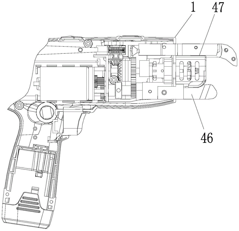
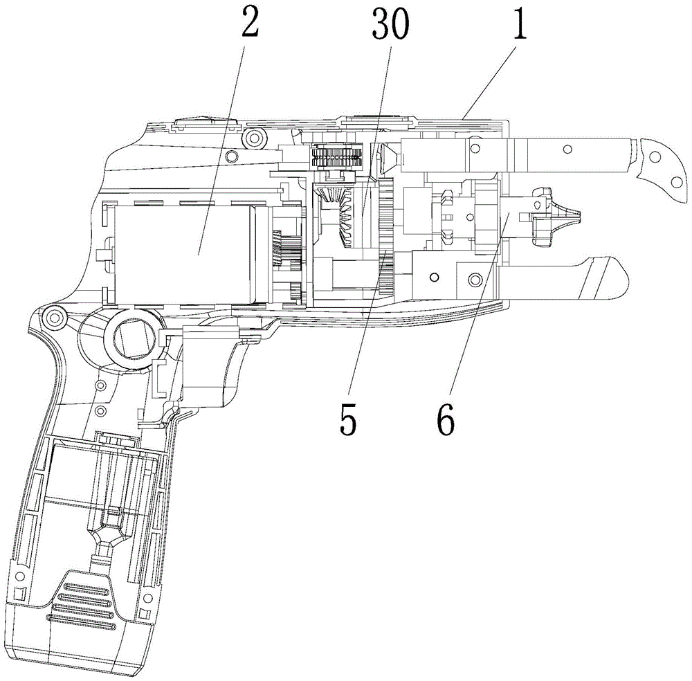
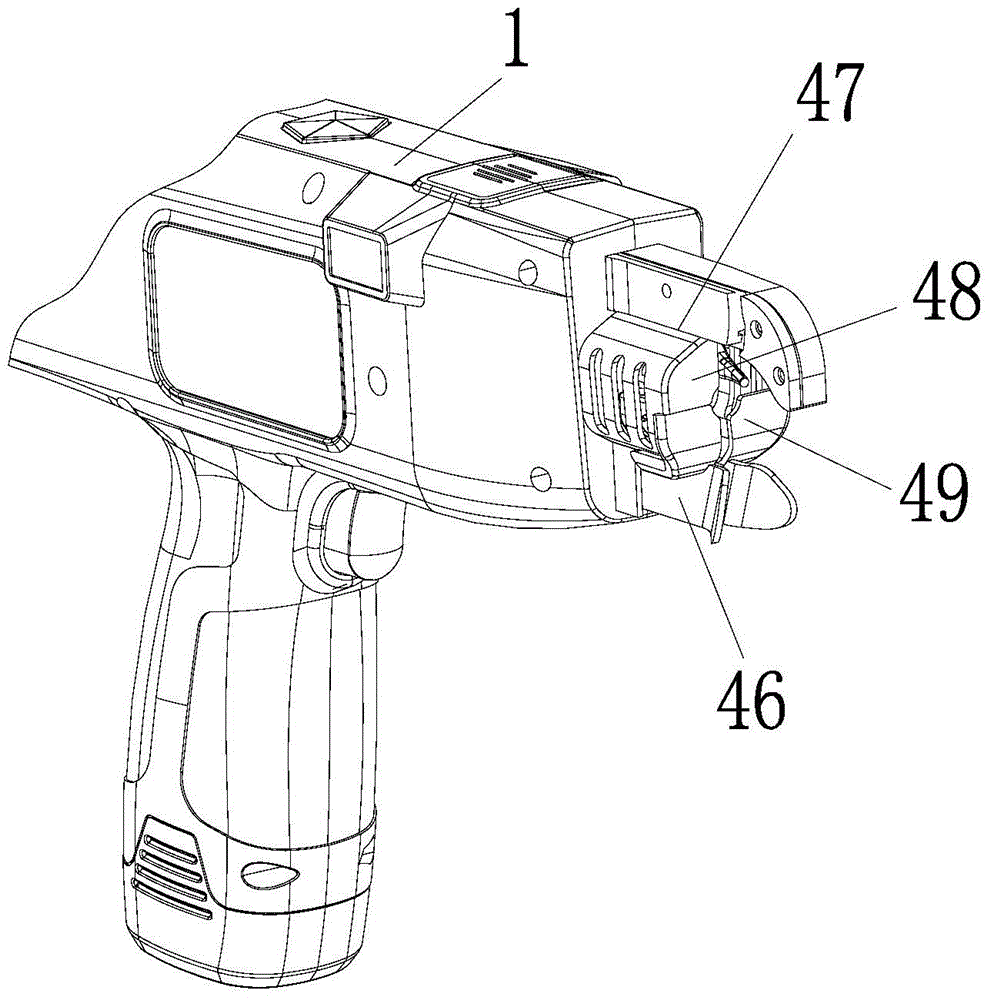
[0049] An automatic steel bar binding machine, comprising a casing 1, a motor 2, a wire feeding mechanism 3, a wire cutting mechanism 4, a transmission system 5 and a wire twisting mechanism 6, the twisting mechanism 6 includes a rotating rod 7, a chuck 8, an anti-off Mechanism 9, sleeve 10 and spring 11, said rotating rod 7 has threaded section 12, and said collet 8 comprises collet body 13 and twisted wire claw 14, and collet body 13 has spring chamber 15 at one end, and the other end is connected with The twisted claws 14 are hinged, the spring 11 is installed in the spring chamber 15, and the front end of the rotating rod 7 extends into the spring chamber 15 of the collet body 13 and is connected to the spring chamber 15 and the spring 11 through the anti-off mechanism 9. connected;

[0050] The outer surface of the sleeve 10 has a transmission toothed belt, and the transmission toothed belt includes one long tooth 16 and seven short teeth 17, and the inner surface of the ...

Embodiment 2

[0067] This embodiment differs from Embodiment 1 in that: the transmission system 5 includes a buffer mechanism 30 and a power input gear 31, and the power input gear 31 has an arc-shaped first buffer chute 32 on one side, and the buffer mechanism 30 It includes an output wheel 33 and a buffer wheel 37. A first transmission block 34 protrudes from one side of the output wheel 33, a second transmission block 38 protrudes from one side of the buffer wheel 37, and an arc-shaped first transmission block 38 protrudes from the other side. Two buffer chute 39, the second transmission block 38 is connected in the first buffer chute 32, and the first transmission block 34 is connected in the second buffer chute 39;

[0068] The sum of the radians of the first buffer chute 32 and the second buffer chute 39 is equal to or greater than the angle at which the rotating rod 7 makes the twisting claw 14 rotate from being tightly hugged to being opened;

[0069] The rotating rod 7 is transmiss...


PUM


Abstract

The invention discloses an automatic rebar tying machine comprising an outer shell and a wire twisting mechanism. The wire twisting mechanism comprises a rotating rod, a chuck, a disengagement preventing mechanism, a sleeve and a spring. The rotating rod is provided with a thread section. The chuck comprises a chuck body and wire twisting claws. A spring bin is arranged at one end of the chuck body. The other end of the chuck body is hinged to the wire twisting claws. The spring is installed in the spring bin. The front end of the rotating rod stretches into the spring bin of the chuck body, is connected with the interior of the spring bin through the disengagement preventing mechanism and is connected with the spring. A conveying tooth belt is arranged on the outer surface of the sleeve and comprises a long tooth and a plurality of short teeth. The inner surface of the sleeve is provided with threads in fit connection with the thread section on the rotating rod. The rotating rod and the chuck body are connected to the interior of the sleeve respectively. The wire twisting claws are hinged to the sleeve. A lower pawl-type wide limiting piece and an upper pawl-type narrow limiting piece are arranged at the position, corresponding to the conveying tooth belt, of the outer shell. The automatic rebar tying machine is compact in structure and can feed wire and twist wire accurately.

Description

technical field [0001] The invention relates to the field of steel bar binding, in particular to an automatic steel bar binding machine. Background technique [0002] With the continuous increase of domestic labor costs in recent years, at the same time, people have more and more demands on the working environment and labor intensity, especially the high-intensity labor and difficult working environment in the construction industry. Similarly, in developed countries in Europe and the United States, companies not only have to deal with high labor costs, low work efficiency and work quality, but also have to deal with many demands such as personal dissatisfaction with work intensity. Therefore, how to realize industrial automation has become an important issue in the development of the whole society. Therefore, high-efficiency and low-strength production tools are gradually accepted by people, including automatic steel bar binding machines. Yet, because existing automatic ste...

Claims


Application Information

Patent Timeline
Patent Type & Authority Patents(China)
IPC IPC(8): E04G21/12
Inventor 易映国李移清
Owner GUANGDONG SHUNDE HUAYAN ELECTRONICS TECH CO LTD
Why Eureka
Try Eureka