Building fabricated concrete wall body and main body structure connecting device

A technology for concrete walls and main structures, applied in building components, building structures, buildings, etc., can solve the problems of high precision requirements of walls and main structures, affecting installation, time-consuming and laborious, and reducing the probability of structural cracks. Enhance the overall stability and enhance the effect of the knot effect

Pending Publication Date: 2020-10-16
QINGDAO ZHONGJIAN COMBINATION CONSTR ENG CO LTD
View PDF10 Cites 0 Cited by
  • Summary
  • Abstract
  • Description
  • Claims
  • Application Information

AI Technical Summary

Problems solved by technology

[0002] The connection between the wall and the main body is very important in the installation and construction of the prefabricated concrete wall. At present, the connection between the prefabricated concrete wall and the main structure is mostly sleeve grouting connection. This connection method is very important for the wall and the main structure. The accuracy requirements are too high, the installation is too difficult, time-consuming and laborious, and it is extremely difficult to operate, and the components are easily deformed and damaged during transportation and hoisting, which will affect the installation and cause certain economic losses. At the same time, once the grouting is not full or There are quality problems. Under the action of an earthquake, the steel bars are likely to be pulled out of the sleeve, which poses a structural safety hazard.

Method used


Image

  • Building fabricated concrete wall body and main body structure connecting device
  • Building fabricated concrete wall body and main body structure connecting device
  • Building fabricated concrete wall body and main body structure connecting device

Examples


Embodiment Construction

[0016] The present invention will be further elaborated below in conjunction with the accompanying drawings and specific embodiments.

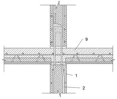
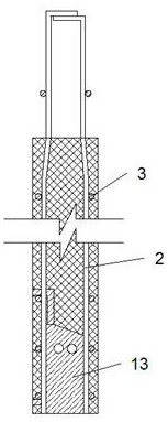
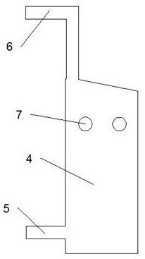
[0017] Such as Figure 1-6 As shown, a building assembly type concrete wall and the main structure connection device, including concrete wall 1, longitudinal bent anchor steel bar 2, transverse steel bar 3, reserved grouting chamber 4, grouting hole 5, paddle row hole 6, Reservoir piercing holes 7, reserved grooves 8, and connecting parts 9. The interior of the concrete wall 1 has a plurality of longitudinal bent anchor bars 2, and the tops of each of the longitudinal bent anchor bars 2 are welded to each other up and down. Longitudinal bent anchor reinforcement bars 2 are bundled with a plurality of horizontal transverse reinforcement bars 3 in the vertical direction, a plurality of vertical reserved grouting bins 4 are fixed at the bottom of the concrete wall body 1 , and a left end of the bottom of the concrete wall body 1 is fixed with a ...


PUM


Abstract

The invention discloses a building fabricated concrete wall body and main body structure connecting device. The building fabricated concrete wall body and main body structure connecting device comprises a concrete wall body, a plurality of longitudinal bent anchor steel bars, a plurality of transverse steel bars, a reserved grouting bin, a grouting hole, a slurry discharging hole, reserved steel bar penetrating holes, a reserved groove and a connecting part, wherein the longitudinal bent anchor steel bars are fixedly arranged inside the concrete wall body, the tops of the longitudinal anchor bent steel bars are welded up and down, and a plurality of horizontal transverse steel bars are bundled up in the vertical direction of each longitudinal anchor bent steel bar. The two concrete walls are connected through grouting materials and perforated pin key bars, and the perforated pin key bars are located below the two longitudinal bent anchor steel bars, so that the stress effect can be achieved, the pulling effect of the walls is enhanced, the probability that structural cracks are generated at the joint of the two concrete walls is reduced, then the overall stability is enhanced, andthe probability that the longitudinal anchor bent steel bars are drawn out of the grouting bin under the action of horizontal external force such as earthquake is reduced, and potential safety hazardsin a structure are reduced.

Description

technical field [0001] The invention relates to the field of building construction, in particular to a device for connecting a building assembly type concrete wall and a main structure. Background technique [0002] The connection between the wall and the main body is very important in the installation and construction of the prefabricated concrete wall. At present, the connection between the prefabricated concrete wall and the main structure is mostly sleeve grouting connection. This connection method is very important for the wall and the main structure. The accuracy requirements are too high, the installation is too difficult, time-consuming and laborious, and it is extremely difficult to operate, and the components are easily deformed and damaged during transportation and hoisting, which will affect the installation and cause certain economic losses. At the same time, once the grouting is not full or There are quality problems. Under the action of an earthquake, the stee...

Claims


Application Information

Patent Timeline
IPC IPC(8): E04B1/38E04B1/41E04B1/98E04H9/02
CPCE04B1/38E04B1/41E04B1/98E04H9/02
Inventor 曲中宝王砚廷张启广于文峰刘京林
Owner QINGDAO ZHONGJIAN COMBINATION CONSTR ENG CO LTD
Why Eureka
Try Eureka