Steel bar connecting machine

A technology for connecting machines and steel bars, which is applied in construction, building construction, and processing of building materials. It can solve the problems of reducing labor efficiency, high labor intensity, and increasing labor costs, and achieve the goal of reducing labor intensity and improving work efficiency. Effect

Active Publication Date: 2015-04-22
河北蓝堡住宅工业有限公司
View PDF9 Cites 10 Cited by
  • Summary
  • Abstract
  • Description
  • Claims
  • Application Information

AI Technical Summary

Problems solved by technology

However, in the current construction site, the connection between the steel bar and the sleeve is manually completed by the worker with a wrench. The labor intensity is very high. Due to the limitation of the operating space, the worker must loosen the wrench to tighten the steel bar after twisting the wrench at a certain angle. Clamping, turning an angle, and then re-clamping the steel bar, twisting the steel bar back and forth in this way, and finally tightening the steel bar and the sleeve, so it is time-consuming and laborious, and the efficiency is extremely low, which increases the labor time of workers, reduces labor efficiency, and increases labor cost

Method used


Image

  • Steel bar connecting machine
  • Steel bar connecting machine
  • Steel bar connecting machine

Examples


Embodiment Construction

[0024] Below in conjunction with accompanying drawing and embodiment the present invention will be further described:

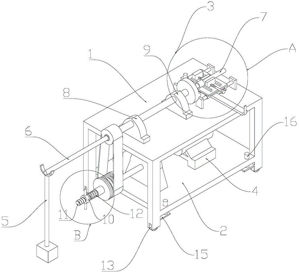
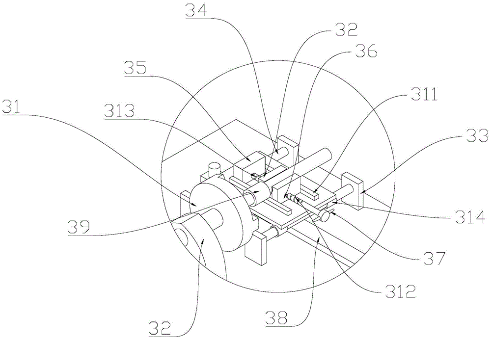
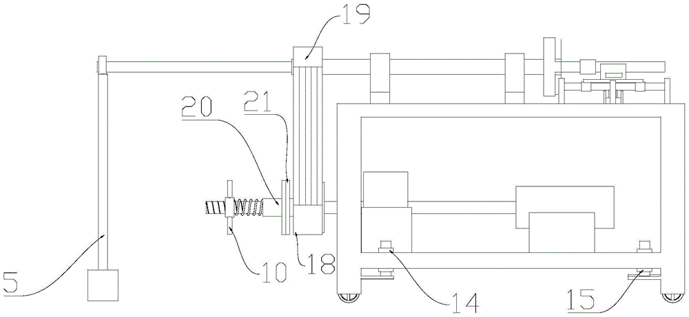
[0025] Such as Figure 1 to Figure 8 A steel bar connecting machine shown includes a frame body with a working platform 1, and the working platform 1 is provided with an axially slidable positioning and clamping seat 3 for clamping a fixed-end steel bar 7, and the positioning and clamping The axial direction of the seat 3 is also provided with a first bearing seat 9 and a second bearing seat 8 in sequence, and a driven shaft is connected between the two bearing seats, and the driven shaft is provided with a through hole for accessing the rotating end. The through hole of the steel bar 6, the driven shaft is connected with a three-jaw chuck 31 for clamping the rotating end steel bar 6 at one end close to the positioning clamping seat 3, and the other end of the driven shaft is connected with a driven wheel 19; the steel bar connecting machine It also includes...


PUM


Abstract

The invention discloses a steel bar connecting machine which comprises a machine frame body with a working platform. A positioning and clamping base which clamps steel bars at the fixed end and can axially slide is arranged on the working platform. A first bearing pedestal and a second bearing pedestal are arranged on the positioning and clamping base in the axis direction. A driven shaft is arranged between the two bearing pedestals in a connected mode. The driven shaft is provided with a through hole where steel bars at the rotating end can penetrate. The end, close to the positioning and clamping base, of the driven shaft is connected with a three-jaw chuck for clamping the steel bars at the rotating end. The other end of the driven shaft is connected with a driven wheel. The steel bar connecting machine further comprises a driving motor. The driving motor drives a driving wheel to rotate. The driving wheel drives the driven wheel to rotate. The steel bar connecting machine has the advantages that the steel bars and sleeves can be rapidly fastened, the labor intensity of workers can be lowered, and the working efficiency can be improved.

Description

technical field [0001] The invention relates to a steel bar connecting machine for connecting two steel bars with a sleeve. Background technique [0002] In the construction industry, traditional steel bar connections include lap joints, welding, etc., but they cannot meet the needs of the rapid development of the construction industry in terms of connection quality, efficiency or operability. In recent years, the method of connecting steel bars in series by using steel bar connecting sleeves with internal threads has been widely used. For example, a connecting sleeve disclosed in patent CN201915561U, two steel bars are respectively screwed on both ends of the steel bar connecting sleeves, thereby Realize the butt joint of two steel bars along the length direction. However, in the current construction site, the connection between the steel bar and the sleeve is manually completed by the worker with a wrench. The labor intensity is very high. Due to the limitation of the ope...

Claims


Application Information

Patent Timeline
Patent Type & Authority Applications(China)
IPC IPC(8): E04G21/12
Inventor 谭斌鲁雪华
Owner 河北蓝堡住宅工业有限公司
Why Eureka
Try Eureka