
Active Compensation Low Eddy Current Axial Air Bearing

An air bearing and active compensation technology, which is applied in the direction of shafts and bearings, bearings, mechanical equipment, etc., can solve the problems of difficult execution, long cycle, and limited accuracy improvement, and achieve convenient execution, improve rotary positioning accuracy, and adjust The effect of simple process

Active Publication Date: 2017-02-22
HARBIN INST OF TECH +1
View PDF9 Cites 0 Cited by
  • Summary
  • Abstract
  • Description
  • Claims
  • Application Information

AI Technical Summary

Problems solved by technology

[0004] The purpose of the present invention is to solve the problem that the accuracy of the air bearing is improved by repeated detection, grinding and assembly, the implementation is difficult and the cycle is long, and the accuracy improvement range is limited, and an active compensation type low-eddy axial-moving air bearing is provided. bearing

Method used


Image

  • Active Compensation Low Eddy Current Axial Air Bearing
  • Active Compensation Low Eddy Current Axial Air Bearing
  • Active Compensation Low Eddy Current Axial Air Bearing

Examples


specific Embodiment approach 1

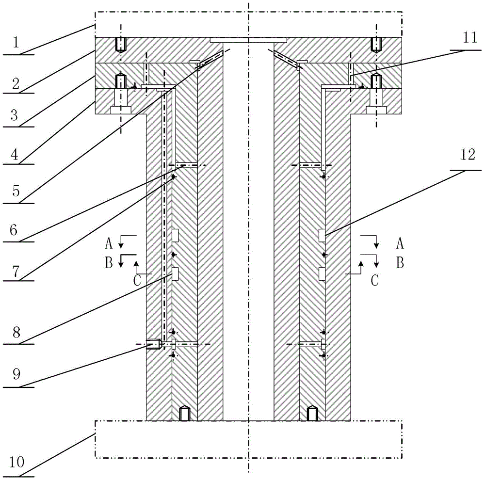
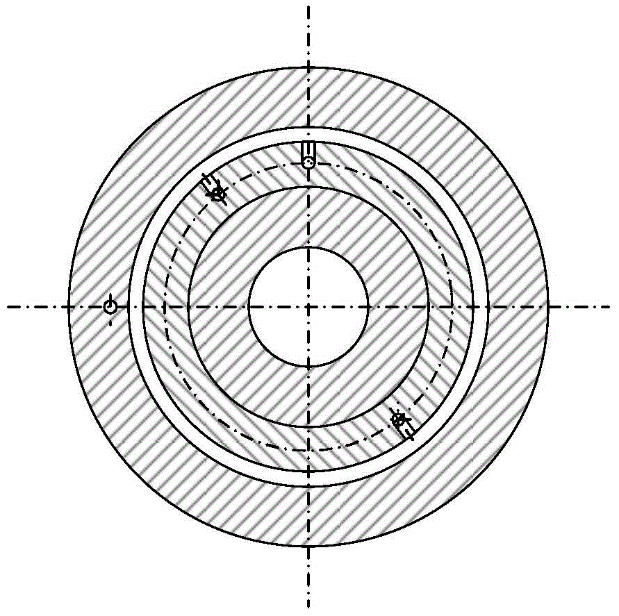
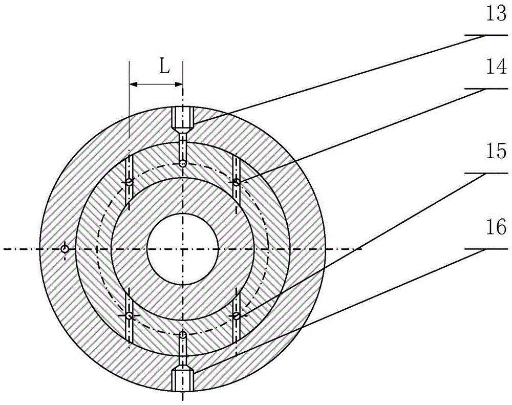
[0023] Specific implementation mode one: the following combination Figure 1 to Figure 4 Describe this embodiment, the active compensation type low eddy current axial motion air bearing in this embodiment, the air bearing is installed between the load 1 and the base 10, and is used to realize the high precision of the load 1 relative to the base 10 rotary motion;

[0024] The air bearing includes an air bearing shaft 2, an air bearing sleeve 3, an air sealing sleeve 4, a vent hole 5, a radial orifice 6, an O-ring 7, a clockwise active vortex air supply chamber 8, and an air bearing. Floating bearing air supply hole 9, thrust surface throttle hole 11, counterclockwise active vortex air supply cavity 12, counterclockwise active vortex air supply hole 13, counterclockwise active vortex non-radial orifice 14, clockwise active vortex non-radial To the orifice 15 and the clockwise active swirl air supply hole 16,

[0025] The air bearing shaft 2 is a T-shaped shaft or an I-shaped ...

specific Embodiment approach 2

[0035] Embodiment 2: This embodiment further describes Embodiment 1. The load 1 is a rotor of a turntable or a rotating shaft of a precision shafting system.

specific Embodiment approach 3

[0036] Embodiment 3: This embodiment further describes Embodiment 1 or 2. The base 10 is the peripheral structure of the table body of the precision turntable or the housing of the precision shafting system.

[0037] Combine below Figure 5 Interference eddy current moment compensation method of the present invention is described:

[0038] According to the geometric dimensions and tooling conditions of the air bearing, the empirical value T of the air bearing disturbance torque is given, and the parameters M, N and L are designed so that the active eddy current Ta≥1.5T is generated by the non-meridional orifice of the active eddy current.

[0039] The disturbance eddy current compensation process of the air bearing is as follows:

[0040] Step 1. Complete the processing and assembly of each part of the air bearing;

[0041] Step 2. Ventilate the radial orifice of the air bearing and the orifice of the thrust surface, and observe whether the air bearing rotates by itself;

...


PUM


Abstract

The invention relates to an active compensation type air bearing, belonging to the technical field of air floating ultra-precision bearings and aiming at solving the problems that improvement of the precision of the air bearings by using repeated detection, grinding and assembly is large in implementation difficulty and long in period and the improved precision is limited. The active compensation type low-swirl shaft-driven air bearing is arranged between a load and a base and used for achieving the high precision rotary movement of the load relative to the base; the air bearing comprises an air shaft, an air shaft sleeve, an air sealing sleeve, an air relief hole, a radial throttle hole, an O-shaped sealing ring, a clockwise active swirl air supply cavity, an air bearing supply hole, a thrust face throttle hole, a counterclockwise active swirl air supply cavity, a counterclockwise active swirl air supply hole, a counterclockwise active swirl nonradial throttle hole, a clockwise active swirl nonradial throttle hole and a clockwise active swirl air supply hole. The active compensation type low-swirl shaft-driven air bearing is an active compensation type air bearing.

Description

technical field [0001] The invention relates to an active compensation type low eddy current axial-moving air bearing, and belongs to the technical field of air bearings of ultra-precision bearings. Background technique [0002] Air bearings are widely used in high-precision measuring instruments, manufacturing equipment and experimental systems such as precision turntables. Traditional air bearings spray high-pressure gas through radial orifices, forming a high-pressure gas film between the shaft and the sleeve, realizing the non-contact rotary motion of the shaft and the sleeve, reducing the friction and other interference torque during the rotary motion of the shaft, Realize micro-disturbance high-precision rotary motion. Due to processing and assembly errors, the orifice is not a precise round hole, and it is even more difficult to accurately locate it in the radial direction. The shape and position error of the orifice is due to the fact that when the orifice ejects hi...

Claims


Application Information

Patent Timeline
Patent Type & Authority Patents(China)
IPC IPC(8): F16C32/06
Inventor 刘延芳齐骥刘兴富齐乃明于灵慧黄琳
Owner HARBIN INST OF TECH
Learn More