On-off time area method heat metering system

A technology of on-off time area and metering system, which is applied in heating systems, household heating, household heating, etc., can solve the problems of affecting heat allocation and charging, unsatisfactory use effect, and cost increase, so as to reduce heat allocation Unreasonable, the result is more scientific and reasonable, and the effect of reducing the amount of installation

Active Publication Date: 2015-04-22
长春净月潭供热有限公司
View PDF5 Cites 15 Cited by
  • Summary
  • Abstract
  • Description
  • Claims
  • Application Information

AI Technical Summary

Problems solved by technology

However, many deficiencies in the system have been found in actual use. The first is that the cost of the system is relatively high (including the cost of the product itself, construction and installation, and supporting projects). In order to supply power to the on-off controller in the system, it is basically to install a power supply for each unit. In this way, not only the cost itself is increased, but also an electric energy metering device needs to be installed in each unit to measure the heat of the unit. The electric energy consumed by the metering system greatly increases the cost of the entire system; in addition, the on-off controller in the current system basically uses one for each household, corresponding to the user one by one, and the cost is also high
The second is that the heat allocation error is relatively large, especially when the user's heating system cannot meet the standard requirements, the error will be even greater, which directly affects the heat allocation and charging
According to the requirements of "Technical Conditions for On-off Time Area Method Heat Metering Device",

Method used


Image

  • On-off time area method heat metering system
  • On-off time area method heat metering system
  • On-off time area method heat metering system

Examples


Embodiment Construction

[0014] The present invention will be further described below using the drawings and specific embodiments.

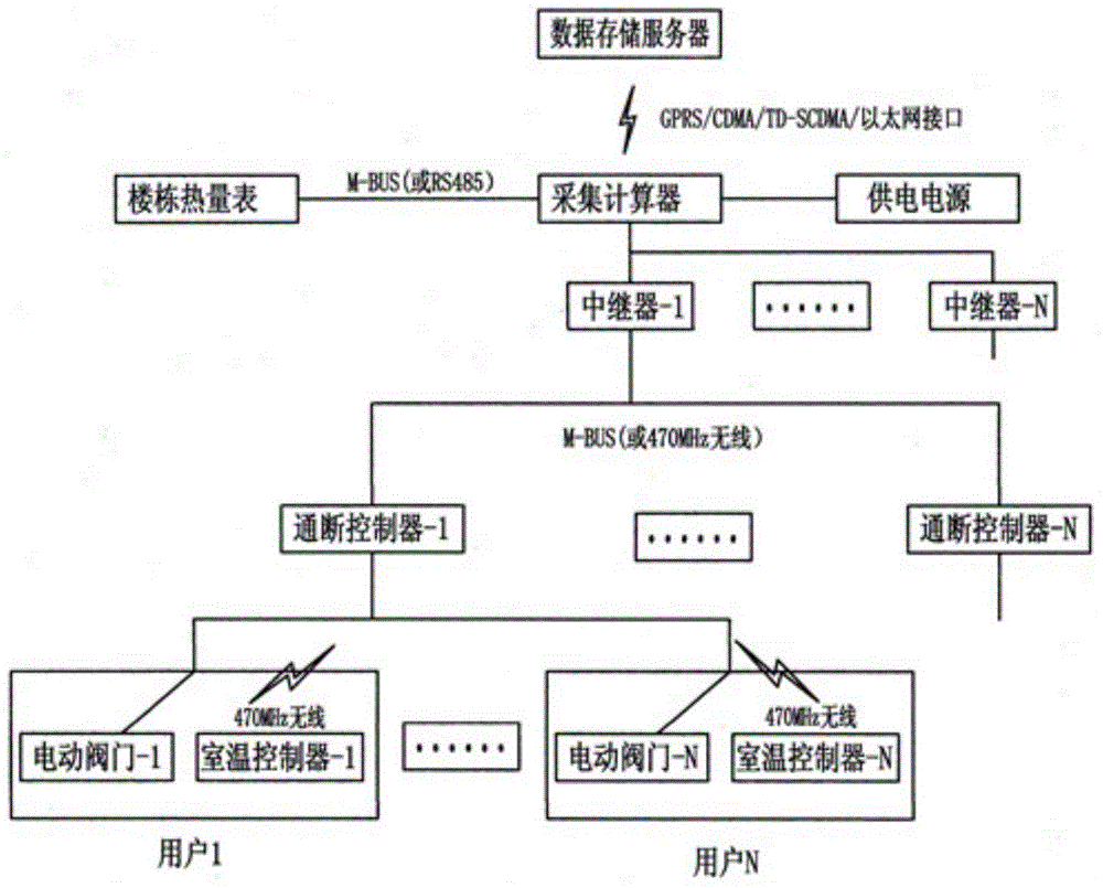
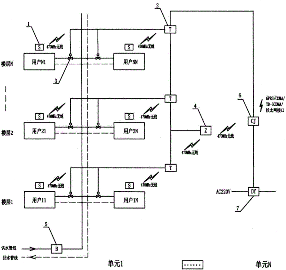
[0015] refer to figure 1 and figure 2 , an on-off time-area heat metering system of the present invention includes a room temperature controller 1, an on-off controller 2, an electric valve 3, a repeater 4, a building heat meter 5, a collection calculator 6, a power supply 7 and Data storage server. The room temperature controller 1 is fixedly installed in the user's room, one for each household, and the installation location of the same type of users in a building should be the same or similar. The room temperature controller 1 is equipped with an anti-movement device. To move by itself to ensure the fairness of heat sharing, the room temperature controller 1 communicates with the on-off controller 2 through 470MHz wireless. The on-off controller 2 is installed outside the user's room. The on-off controller 2 has the function of dragging multiple devices. One ...


PUM


Abstract

The invention is an on-off time area method heat metering system which is characterized in that an indoor temperature controller is fixedly installed in a room of a user and provided with an anti-moving device, an on-off controller has a multi-split function, the users on the same floor share a on-off controller, an EOV (electrically operated valve) is installed on a heat supplying main pipeline of the users, a building heat meter is installed the main pipeline of a building heat supplying system, an acquisition calculator is installed on the middle floor of a middle unit of a building, the system adopts a centralized power source for supplying power, wireless communication is adopted among the indoor temperature controller, the on-off controller, a repeater and the acquisition calculator, and wire communication is adopted between the building heat meter and the acquisition calculator. The system adopts the centralized power source to supply power for the system, the on-off controller is of a multi-split mode, the entire construction cost of the system is reduced greatly, simultaneously, the system can amend the quantity of heat apportioned by the on-off time area method according to the indoor temperature situation of the user, which makes charging more scientific and reasonable.

Description

technical field [0001] The invention relates to the technical field of heat supply metering, in particular to an on-off time area method heat metering system. Background technique [0002] The on-off time area method heat metering system is one of the main heat metering methods implemented in the current heat metering reform. It can not only apportion the heat consumption of the building, but also adjust and control the user's indoor temperature to achieve energy saving. At the same time, it can upload the user's indoor temperature, which provides important information for the production of thermal power enterprises. Therefore, it has been widely promoted and used in many domestic provinces and cities. However, many deficiencies in the system have been found in actual use. The first is that the cost of the system is relatively high (including the cost of the product itself, construction and installation, and supporting projects). In order to supply power to the on-off contr...

Claims


Application Information

Patent Timeline
IPC IPC(8): F24D19/10
Inventor 王跃进王素艳张剑平牟宗峰刘明宇宋帛轩张颖张伟
Owner 长春净月潭供热有限公司
Why Eureka
Try Eureka