
An on-orbit unlocking device for a space optical remote sensor installation support

A space optical remote sensing and mounting support technology, applied in the field of space optics, can solve the problems of large space occupation, easy generation of pollutants, and heavy weight, so as to reduce the difficulty of processing and assembly, save cost and development cycle, reduce The effect of weight and space

Active Publication Date: 2017-06-09
CHANGCHUN INST OF OPTICS FINE MECHANICS & PHYSICS CHINESE ACAD OF SCI
View PDF8 Cites 0 Cited by
  • Summary
  • Abstract
  • Description
  • Claims
  • Application Information

AI Technical Summary

Problems solved by technology

[0008] The purpose of the present invention is to provide an on-rail unlocking device for space optical remote sensor installation support, which solves the problem of prior art processing, high requirements for assembly and adjustment, high precision requirements, long development cycle, high cost, large impulse, large weight, and space occupation. Large, easy to produce pollutants, and there are potential safety hazards

Method used


Image

  • An on-orbit unlocking device for a space optical remote sensor installation support
  • An on-orbit unlocking device for a space optical remote sensor installation support
  • An on-orbit unlocking device for a space optical remote sensor installation support

Examples


Embodiment Construction

[0019] The present invention will be further elaborated below in conjunction with the accompanying drawings.

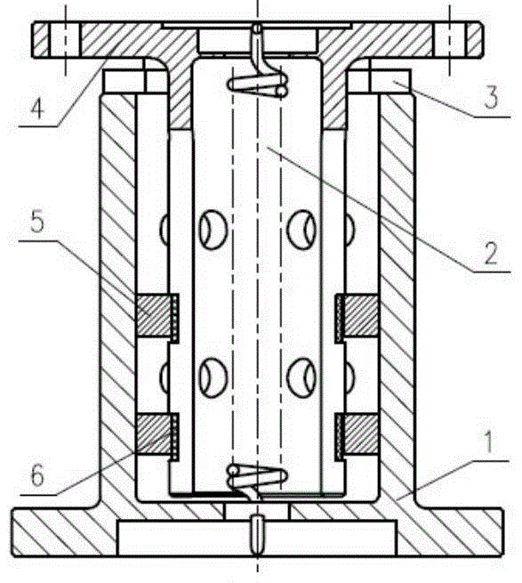
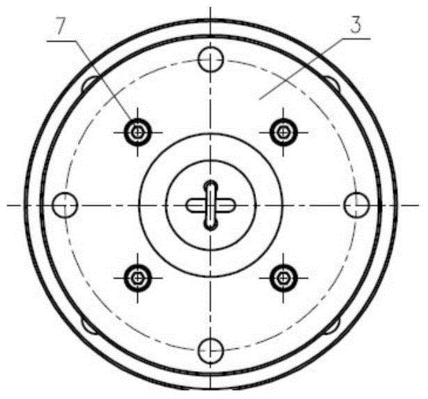
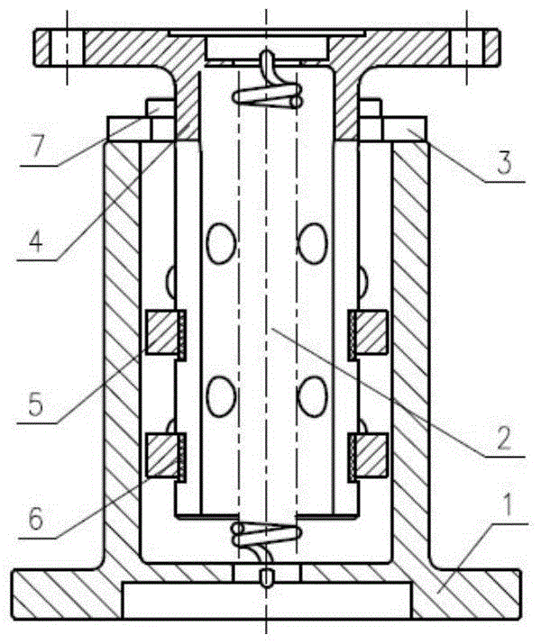
[0020] See attached figure 1 , attached figure 2 , attached image 3 And attached Figure 4 , an on-rail unlocking device for a space optical remote sensor mounting support of the present invention includes a mounting support lower body 1, a tension spring 2, a mounting support upper body 4, a telescopic ring 5, a heat insulation pad 6 and a heating sheet; the mounting support The lower body 1 is set on the upper body 4 of the installation support, the tension spring 2 is between the upper body of the support and the lower body 1 of the installation support, one end of the tension spring 2 is hooked on the upper body 4 of the installation support, and the other end is hooked on the On the lower body of the installation support, the lower body 1 of the installation support is connected with the satellite, and the upper body 4 of the installation support is connecte...


PUM


Abstract

The invention relates to an on-rail unlocking device for a mounting support of a space optical remote sensor, which belongs to the field of space optics technology, and solves the problem of high processing, assembly and adjustment requirements, high precision requirements, long development cycle, high cost, large impulse and heavy weight in the prior art. 1. It takes up a lot of space, easily produces pollutants, and has potential safety hazards; the device includes the lower body of the mounting support used to connect with the satellite, the limit half-circle connected with the lower body of the mounting support, and the space optical remote sensor. The upper body of the installation support, the tension spring connected with the lower body of the installation support and the upper body of the installation support, the heat insulation pad contacted with the upper body of the installation support, and the telescopic ring for pressing the heat insulation pad. There are 2 limit semi-circular rings in total, which are connected to the lower body of the mounting support by means of hexagon socket screws. There are 8 pieces of heat insulation pads in total, which have telescopic function, and are sandwiched between the two telescopic rings and the upper body of the mounting support. The telescopic rings are made of memory alloy. Material, the non-contact surface of the telescopic ring has a heating plate, when heated, the telescopic ring shrinks.

Description

technical field [0001] The invention belongs to the technical field of space optics, and in particular relates to an on-rail unlocking device for a mounting support of a space optic remote sensor. Background technique [0002] As a high-precision spaceborne optical device, the space optical remote sensor is particularly sensitive to stress, and the ground installation and launch environment will inevitably introduce some stress, especially during the installation process of the space optical remote sensor and satellite, the introduction of assembly stress is the largest, so the design It is imperative to have a set of mounting support on-rail unlocking device. At present, the on-orbit unlocking device of space optical remote sensor mainly adopts pyrotechnic detonation method, which has the following disadvantages: [0003] 1) High requirements for processing and assembly, high precision requirements, and long development cycle. The structure of the pyrotechnic detonation d...

Claims


Application Information

Patent Timeline
Patent Type & Authority Patents(China)
IPC IPC(8): G01D11/00G01D11/30
Inventor 柴方茂樊延超辛宏伟李志来张学军
Owner CHANGCHUN INST OF OPTICS FINE MECHANICS & PHYSICS CHINESE ACAD OF SCI
Learn More