Small-size lifesaving antenna

A small size, antenna technology, applied in the direction of antennas, antenna equipment with additional functions, radiating element structure, etc., can solve the problems of easy swing of antenna, scratches and collisions, scratches and collisions of external objects of antennas, etc., to achieve reduction Effect of small waves, reduced effective length, and simple structural design

Inactive Publication Date: 2015-04-22
陕西烽火诺信科技有限公司
View PDF4 Cites 2 Cited by
  • Summary
  • Abstract
  • Description
  • Claims
  • Application Information

AI Technical Summary

Problems solved by technology

[0004] The lifesaving antenna (frequency is 120MHz~123MHz&240MHz~250MHz) is limited by its own frequency band. Generally, the minimum size of the antenna is about 550mm. Because this size is too long, it cannot be installed inside the lifesaving system.
[0005] (2) The antenna is easily scratched and collided by external objects
However, the antenna is placed outside the system and is located at a high point, which is easily scratched and collided by external objects, which will cause damage or even failure of the antenna, and ultimately affect the normal operation of the entire lifesaving system.
[0007] (3) The antenna is easy to swing
Because the antenna itself is a whip antenna, the radiation direction of the antenna is not omnidirectional in space, so that the pattern of the antenna changes during the swing process, which ultimately affects the normal operation of search and rescue.

Method used


Image

  • Small-size lifesaving antenna
  • Small-size lifesaving antenna
  • Small-size lifesaving antenna

Examples


Embodiment Construction

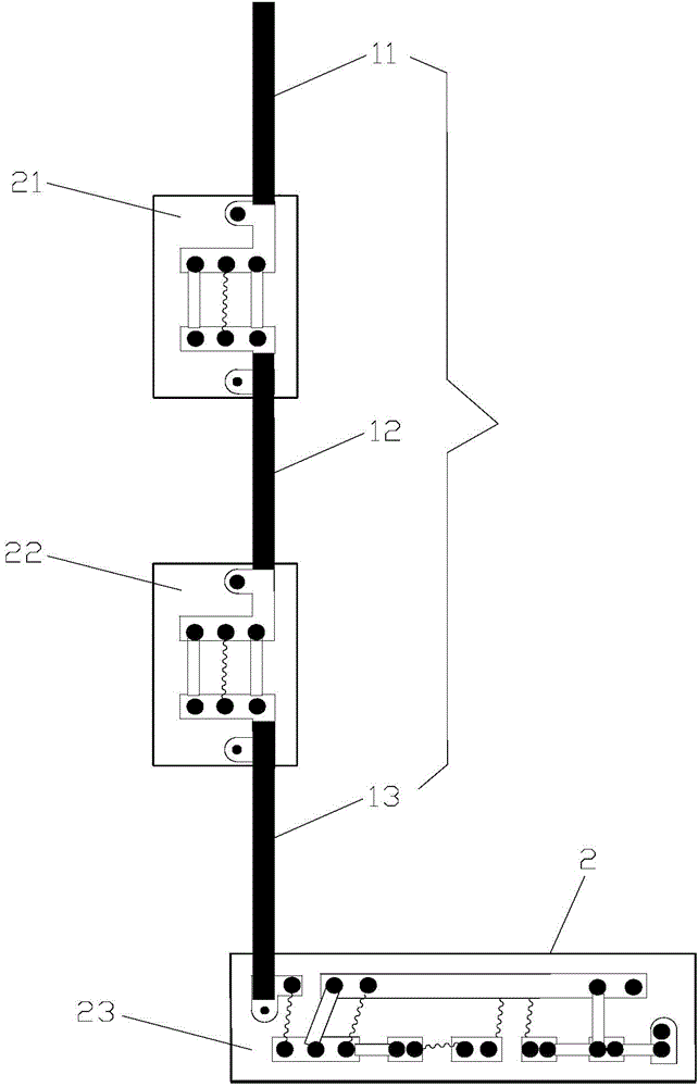
[0032] Such as Figures 1 to 5 As shown, the small-sized rescue antenna of the present invention includes a metal connection conductor 1 and a loading circuit 2 .

[0033] The metal connection conductor 1 is composed of three metal connection conductors with different lengths, that is, a first metal connection conductor 11 , a second metal connection conductor 12 and a third metal connection conductor 13 . The metal connecting conductor 1 adopts a copper rod as a conductor.

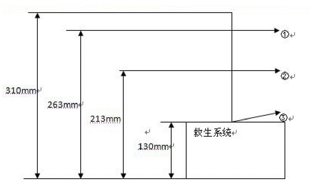
[0034] The loading circuit 2 includes a first loading circuit 21, a second loading circuit 22 and a third loading circuit 23; wherein the first loading circuit 21, the second loading circuit 22 and the third loading circuit 23 are connected to each other through a metal connection conductor 1 ; The distance between the first loading circuit 21 and the second loading circuit 22 is 50 mm; the distance between the second loading circuit 22 and the third loading circuit 23 is 83 mm.

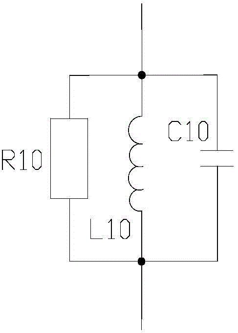
[0035] The first loadi...


PUM


Abstract

The invention relates to a small-size lifesaving antenna which comprises a loaded circuit. The loaded circuit is composed of at least three loaded circuit bodies which are connected through circuit metal connecting conductors. The three loaded circuit bodies are connected with one another through the at least three metal connecting conductors of different lengths. One loaded circuit body comprises a first PCB, a resistor R10, an inductor L10 and a capacitor C10, wherein the resistor R10, the inductor L10 and the capacitor C10 are welded to the first PCB. Another loaded circuit body comprises a second PCB, a resistor R20, an inductor L20 and a capacitor C20, wherein the resistor R20, the inductor L20 and the capacitor C20 are welded to the second PCB. The rest loaded circuit body comprises a third PCB, an inductor L31, an inductor L32, an inductor L33, a resistor R31, a resistor R32, a resistor R33, a capacitor C31, a capacitor C32, a capacitor C33 and a transmission line transformer T, wherein the inductor L31, the inductor L32, the inductor L33, the resistor R31, the resistor R32, the resistor R33, the capacitor C31, the capacitor C32, the capacitor C33 and the transmission line transformer T are welded to the third PCB. The small-size lifesaving antenna is simple and reasonable in structural design, small in size, capable of being arranged in the system, convenient to use, capable of effectively lowering the wave influence of a wind turbine, and capable of meeting the using demands for the small antenna, wide bands and large gains by loading.

Description

technical field [0001] The invention relates to a communication antenna, in particular to a small-sized lifesaving antenna. Background technique [0002] At present, the lifesaving antennas used in my country's surface lifesaving systems are all external whip antennas. This type of antenna has the following disadvantages and problems to be solved: [0003] (1) The size is too long [0004] The lifesaving antenna (frequency ranges from 120MHz to 123MHz & 240MHz to 250MHz) is limited by its own frequency band. Generally, the minimum size of the antenna is about 550mm. Because this size is too long, it cannot be installed inside the lifesaving system. [0005] (2) The antenna is easily scratched and collided by external objects [0006] The antenna should be installed at the highest point of the shell after the lifesaving system is stationary on the water surface, so that the antenna is not shielded and reflected, so as to realize the effective transmission of electromagnetic...

Claims


Application Information

Patent Timeline
Patent Type & Authority Applications(China)
IPC IPC(8): H01Q23/00H01Q1/36H01Q1/44H01Q1/38
Inventor 张志云于汶涛赵艳魏宁强任利媛张雄伟
Owner 陕西烽火诺信科技有限公司
Why Eureka
Try Eureka