Police electronic compass monitoring system

An electronic compass and police technology, which is applied in the field of police electronic compass monitoring system, can solve problems such as limited viewing angle range, unsupported 360-degree panoramic monitoring viewing angle, and affecting the timeliness of case investigation, so as to achieve rapid response and improve efficiency Effect

Inactive Publication Date: 2015-04-22
苏州市吴江区公安局
View PDF17 Cites 4 Cited by
  • Summary
  • Abstract
  • Description
  • Claims
  • Application Information

AI Technical Summary

Problems solved by technology

[0005] At present, most PTZ cameras have a limited range of viewing angles. Although they support 360-degree rotation, they do not support 360-degree panoramic monitoring viewing angles. The direction must be adjusted by operation for real-time monitoring or monitoring at a specific preset position. The public security personnel cannot intuitively know the current monitoring direction of the camera when the camera is imaged, which reduces the quick r...

Method used


Image

  • Police electronic compass monitoring system
  • Police electronic compass monitoring system
  • Police electronic compass monitoring system

Examples


Embodiment Construction

[0020] The implementation of the present invention will be illustrated by specific specific examples below, and those skilled in the art can easily understand other advantages and effects of the present invention from the contents disclosed in this specification.

[0021] see Figure 1 to Figure 4 . It should be noted that the structures, proportions, sizes, etc. shown in the drawings attached to this specification are only used to match the content disclosed in the specification, for those who are familiar with this technology to understand and read, and are not used to limit the implementation of the present invention. Limiting conditions, so there is no technical substantive meaning, any modification of structure, change of proportional relationship or adjustment of size, without affecting the effect and purpose of the present invention, should still fall within the scope of the present invention. The disclosed technical content must be within the scope covered. At the sa...


PUM


Abstract

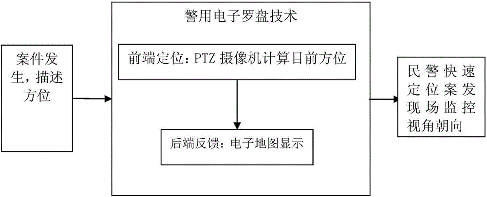
The invention discloses a police electronic compass monitoring system, which comprises a front-end pan-tilt camera positioning platform, a back-end information feedback display platform and a monitoring platform, wherein the monitoring platform is used for reading pan-tilt rotation parameters according to a case occurrence azimuth, converting the pan-tilt rotation parameters to azimuth deviation information after computation and presenting the updated information through a compass icon; a pan-tilt camera is used for adjusting the azimuth and the orientation of the pan-tilt camera according to a pan-tilt control command, collecting a front-end video and outputting the video to a preset pan-tilt camera path; the back-end information feedback display platform is used for loading a real-time video of the pan-tilt camera, locating a target object according to the played video, forecasting a position of the target object at the next computation time and transmitting the position to the pan-tilt camera through the monitoring platform so as to adjust the pan-tilt camera. The system can help a commander to master the monitoring orientation around the scene during real-time commanding and dispatching, so that the patrolling and preventing work as well as the deployment and control work can be carried out quickly, and the case detection efficiency is improved.

Description

technical field [0001] The invention belongs to the technical field of video monitoring, and relates to a police electronic compass monitoring system which is convenient for quickly locating the monitoring direction and writing, commanding and dispatching. Background technique [0002] Due to the vigorous construction of the "Safe City" video surveillance system, public security personnel widely use real-time video surveillance for patrol and control in command and dispatch, and use video surveillance recordings to analyze, judge and solve cases in case detection. [0003] Usually, real-time video monitoring adopts PTZ (abbreviation of Pan / Tilt / Zoom, concept of security monitoring equipment) camera, which represents pan-tilt omni-directional (up and down, left and right) movement and lens zoom and zoom control. Within the scope of the scene monitored by the camera, when a moving target appears, the user can manually lock (such as locking the target by clicking the mouse) or ...

Claims


Application Information

Patent Timeline
IPC IPC(8): H04N7/18
Inventor 丁晓华范建春沈永明金挺陈杰李春红李骁贤
Owner 苏州市吴江区公安局
Why Eureka
Try Eureka