Surface-combustion gas burner

A gas burner and surface combustion technology, which is applied to gas fuel burners, burners, combustion methods, etc., can solve the problems of increasing the total cost of the burner and expensive steel fibers.

Active Publication Date: 2015-04-22
SERMETA
View PDF7 Cites 2 Cited by
  • Summary
  • Abstract
  • Description
  • Claims
  • Application Information

AI Technical Summary

Problems solved by technology

However, steel fibers are expensive, which increases the overall cost of the burner

Method used


Image

  • Surface-combustion gas burner
  • Surface-combustion gas burner
  • Surface-combustion gas burner

Examples


Embodiment Construction

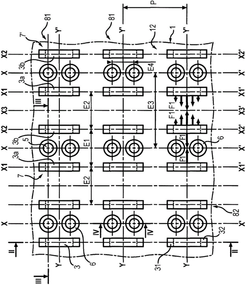
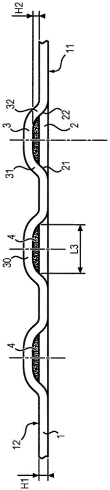
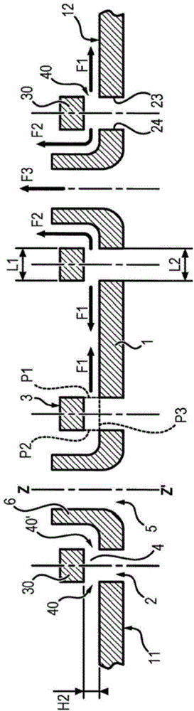
[0048] A first embodiment of a gas burner according to the invention will be referred to Figure 1-4 And is described.

[0049] The burner includes a combustion grid. It is connected to a device (not shown), such as a fan, configured to convey a gas-air mixture under pressure (eg, natural gas and air) into the combustor. The gas mixture passes through the ports and openings of the grid and combustion starts from the outer surface of the combustion grid thanks to an ignition system known to those skilled in the art.

[0050] The combustion grid consists of a sheet (or plate) 1 made of metal, such as stainless steel or of refractory material. The inner and outer surfaces are marked 11 and 12 respectively.

[0051] The sheet 1 is perforated with a series of slits 2 of generally rectangular shape, each slit 2 having two longitudinal edges 23,24.

[0052] Each slot 3 is capped with a bridge 3 or "bridge" which is in one piece (integrated) with the sheet 1 and protrudes from the...


PUM


Abstract

The invention concerns a surface-combustion gas burner comprising a combustion grate consisting of a metal sheet (1) pierced with a series of slots (2). This burner is remarkable in that said metal sheet comprises a series of deflectors (3) made in one piece with said metal sheet and protruding on the outer face (12) of same, each deflector (3) extending longitudinally and laterally above the entire surface of a slot (2), and in that each deflector (3) comprises a guide portion for guiding the gas flow and a junction portion joining to the metal sheet (1), said guide portion being spaced from the metal sheet (1) in such a way as to provide therewith at least one lateral gas ejection port (40, 40'), said deflectors being disposed in pairs in such a way that the lateral gas ejection ports of same face each other.

Description

technical field [0001] The invention belongs to the field of surface combustion gas burners. Background technique [0002] The term "gas burner" refers to a burner that is actually supplied with a premixed gas-air mixture. In the accompanying description and claims, the term "gas" is used for the sake of simplicity to actually refer to a premixed gas-air mixture. [0003] In contrast to flame-breathing burners, so-called "surface burning" burners mean that the combustion takes place on a combustion surface or grid through which the gas-air mixture is guided under pressure. [0004] This type of burner is found especially, but not exclusively, for gas water heaters. Such burners produce combustion gases which heat a heat exchanger through which the fluid to be heated flows. [0005] In gas burners of this type, the flame holding properties on the combustion surfaces determine the quality of combustion of the fuel used (gas in this case) and the power range of the burner. ...

Claims


Application Information

Patent Timeline
Patent Type & Authority Applications(China)
IPC IPC(8): F23D14/58F23D14/70F23D14/02F23D14/26
CPCF23D14/583F23D14/02F23D2900/00012F23D14/70F23D2203/1026F23D14/26F23D14/58F23D2203/104F23D14/145F23D14/586
Inventor J.勒默
Owner SERMETA
Why Eureka
Try Eureka