A household vertical noodle machine

A noodle machine, vertical technology, applied in the direction of dough extruder, mixing/kneading with vertical installation tools, dough forming machinery or equipment, etc., can solve the problem of dough or dough residue, poor customer experience, easy to Residual dough, etc

Active Publication Date: 2016-12-07
JOYOUNG CO LTD
View PDF14 Cites 0 Cited by
  • Summary
  • Abstract
  • Description
  • Claims
  • Application Information

AI Technical Summary

Problems solved by technology

When kneading dough, the stirring rod rotates in the forward direction to mix flour and water into flocs or dough; The noodle inlet on the top of the extruding cylinder falls into the extruding cylinder, and then is extruded by the screw, but there is a problem in this method. In the early stage of extruding, due to the large amount of flour or dough, the stirring teeth are easy to crush the dough. The wadding or dough is scraped up and brought into the noodle extrusion cylinder. In the later stage of noodle extrusion, the wadding or dough becomes less, and the stirring teeth cannot scrape up the wadding or dough, or fall into the mixing cup as soon as it reaches the noodle inlet. , resulting in some flocculation or dough remaining in the mixing cup
[0005] Another example is the vertical noodle machine disclosed by the publication number CN202476367U. Because the stirring rod and the screw rod rotate differently, and the extruding cylinder is located below the stirring cup, the problem of dough residue is well solved, but the existing vertical noodle still exists. Certain problems, when kneading the dough, the stirring rod mixes the flour and water to form flocs or dough; when extruding the dough, because the reconciled flocs or dough are relatively large, it is difficult for the flocs or dough to enter the extruded dough from the noodle inlet In the cylinder, the efficiency is low, and the dough is easy to remain. In order to prevent the dough from remaining, it is necessary to increase the process of manually entering the dough, and the customer experience is not good

Method used


Image

  • A household vertical noodle machine
  • A household vertical noodle machine
  • A household vertical noodle machine

Examples


Embodiment 1

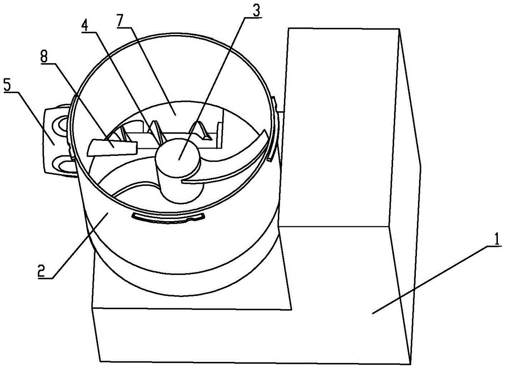
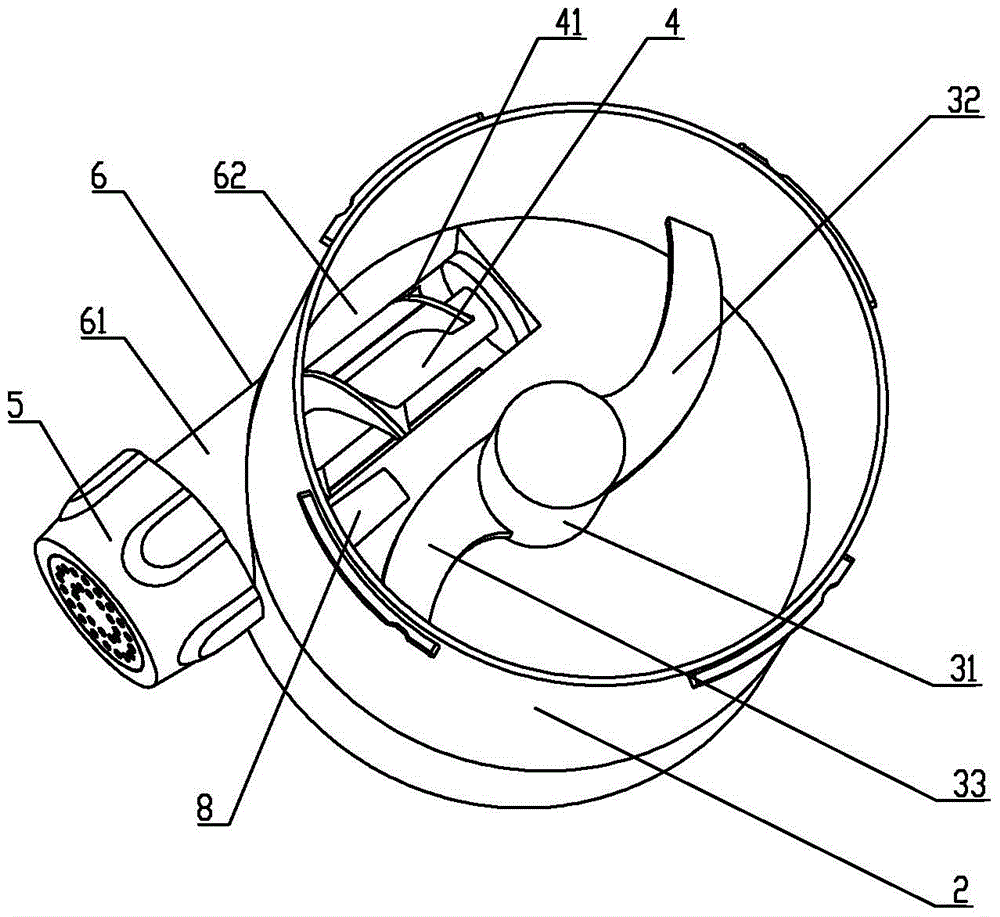
[0039] Such as figure 1 , 2 As shown, the household vertical noodle machine of the present invention includes a base 1, a stirring cup 2 connected to the base 1, a stirring rod 3, a noodle extruding cylinder 6, a screw 4, and a die head 5. A motor (not shown in the figure) and a control unit (not shown in the figure) electrically connected to the motor are provided, and the control unit includes a control circuit module and a circuit detection module.

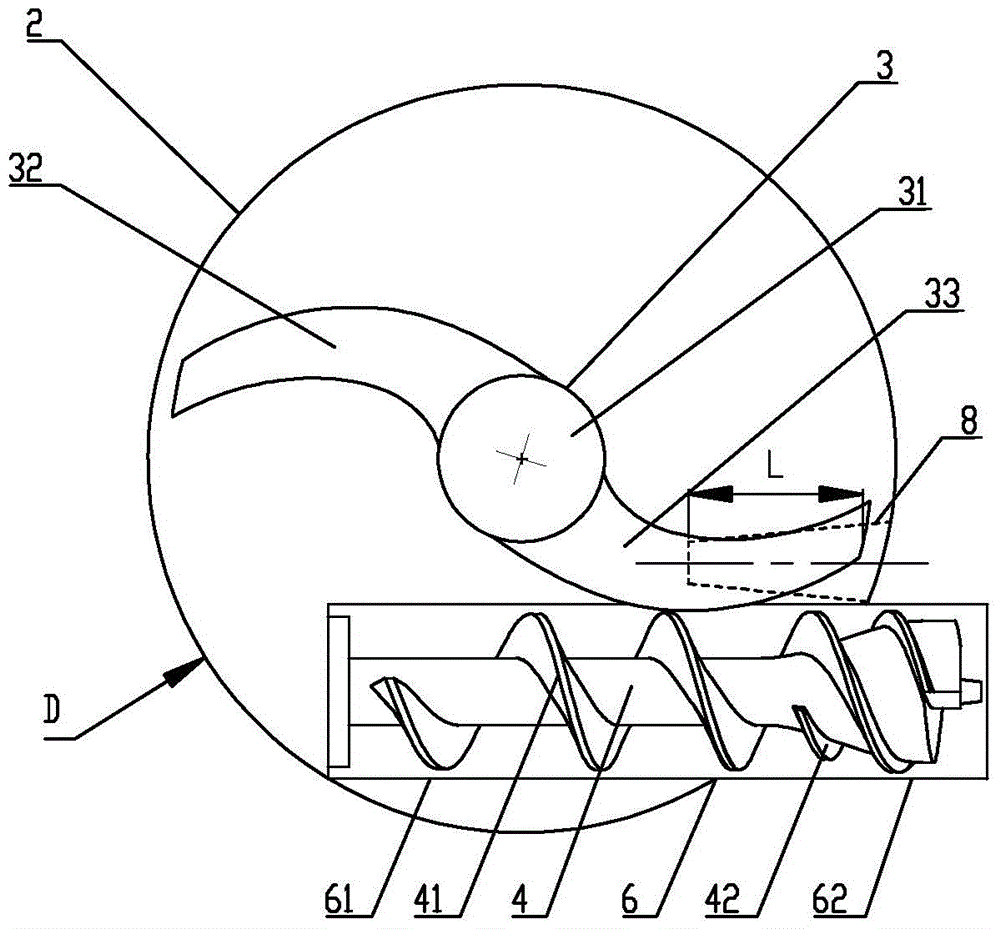
[0040] Such as image 3 As shown, the stirring cup 2 is circular, and the diameter of the stirring cup is D. This setting makes the inner wall of the mixing cup smooth, and the inner wall of the mixing cup will not form a dead corner of the dough when kneading the dough, so as to avoid remaining noodles in the mixing cup.

[0041] The stirring rod 3 is vertically arranged in the stirring cup 2, the stirring rod 3 includes a rod body 31 and an upper stirring tooth 32 and a lower stirring tooth 33 arranged on the rod body 31, ...

Embodiment 2

[0074] The difference between this embodiment and Embodiment 1 is that there are two motors, a first motor and a second motor, the first motor is connected to the stirring rod, and the second motor is connected to the screw.

[0075] The motor (not shown in the figure) includes a first motor (not shown in the figure) and a second motor (not shown in the figure), the first motor is in transmission connection with the stirring rod 3, and the second motor The first motor and the second motor independently drive the stirring rod 3 and the screw 4 to rotate and are independently controlled by the control unit.

[0076] The advantage of this embodiment is that two motors are used, and the screw and the stirring rod are controlled by separate motors, which is easy to control and accurate and reliable.

Embodiment 3

[0078] The difference between this embodiment and the first embodiment lies in that the stirring rod is different.

[0079] Such as Figure 8 As shown, there are two upper stirring teeth 32 located on the same horizontal plane, and the two upper stirring teeth 32 are symmetrically distributed relative to the rod body 31 . There are two lower stirring teeth 33 located on the same horizontal plane, and the two lower stirring teeth 33 are symmetrically distributed relative to the rod body 31 . The two upper stirring teeth 32 and the two lower stirring teeth 33 are integrally formed with the rod body 31 . Of course, they can also be fixed together by secondary injection molding or clamping or screwing or pasting.

[0080]The advantage of this embodiment is that the mixing rod can be cut four times with the dough cutting rod once it rotates, which further improves the dough mixing effect and improves the dough mixing efficiency; at the same time, the dough is cut smaller, making ...


PUM


Abstract

The invention discloses a domestic vertical type noodle maker which comprises a base, a stirring cup, a stirring rod, a dough extrusion cylinder, a screw rod, a mold head and a control unit, wherein the base is provided with motors; the stirring cup is connected with the base; the stirring rod comprises a rod body as well as upper stirring teeth and lower stirring teeth which are arranged on the rod body; a dough inlet is formed in the communicating part of the stirring cup and the dough extrusion cylinder; a dough cutting rod is arranged on the inner wall of the stirring cup; the dough cutting rod is positioned between the upper stirring teeth and the lower stirring teeth; the stirring rod rotates to drive the upper stirring teeth and the lower stirring teeth to rotate and mix and stir flour with water to make dough; the dough cutting rod cooperates with the upper stirring teeth and the lower stirring teeth to cut off or tear and deform the dough into dough pieces which are smaller than the dough inlet; when the upper stirring teeth and / or the lower stirring teeth rotate to the dough cutting rod, the projects of the dough cutting rod and the upper stirring teeth and / or the lower stirring teeth in the horizontal direction are at least partially overlapped. By adopting the mode, the effects of no residue, high possibility of dough feeding and high processing efficiency can be achieved.

Description

technical field [0001] The invention relates to the field of food processing machines, in particular to a household vertical noodle machine. Background technique [0002] With the improvement of living standards, food processors are becoming more and more popular among consumers, and noodle machines are becoming more and more popular among consumers. [0003] Existing noodle machines generally include horizontal noodle machines and vertical noodle machines, and all include machine bases, stirring assemblies and extruding assemblies. head. [0004] As the disclosed horizontal noodle machine with publication number CN103518792A, because the stirring rod and the screw rod rotate coaxially, and the turning radius of the stirring rod is greater than that of the screw rod. When kneading dough, the stirring rod rotates in the forward direction to mix flour and water into flocs or dough; The noodle inlet on the top of the extruding cylinder falls into the extruding cylinder, and ...

Claims


Application Information

Patent Timeline
Patent Type & Authority Patents(China)
IPC IPC(8): A21C11/20
CPCA21C1/02A21C11/20A21C11/22
Inventor 王旭宁苏荣清刘健卢孟林
Owner JOYOUNG CO LTD
Why Eureka
Try Eureka