Ultrasonic-pneumatic nozzle

A spray head and ultrasonic technology, applied in spray devices, liquid spray devices, and devices for capturing or killing insects, etc., can solve the problems of low effective utilization of drugs, threats to people's health, and excessive drug residues, and achieve the benefits of drugs and Nutrient absorption, improving droplet atomization, reducing drug waste

Inactive Publication Date: 2015-04-29
YANGZHOU UNIV
5 Cites 0 Cited by

AI-Extracted Technical Summary

Problems solved by technology

At present, the domestic mechanical pesticide application technology has been hovering at a low level, which is difficult to meet the needs of the market. The effective utilization rate of drugs is low, a l...

Abstract

The invention discloses an ultrasonic-pneumatic nozzle which comprises a spray rod with a tiny liquid flow channel processed in the axis, an ultrasonic generator and a nozzle air tap. A support device is arranged in the middle of the spray rod, the ultrasonic generator is mounted on the support device, the nozzle air tap surrounds the end of the spray rod to form the nozzle, the ultrasonic generator is provided with a piezoelectric wafer, a backseat and a lead, the lead is connected to the piezoelectric wafer, the backseat is located at one end of the piezoelectric wafer and is in contact with the fastening device, the piezoelectric wafer is provided with a piezoelectric ceramic plate and electrode plates, the electrode plates are respectively plated on the front and back sides of the piezoelectric ceramic plate by adopting metallic silver as a conducting material, short pulse of voltage acts on two poles of the piezoelectric wafer through the lead after energization, and due to back voltage effect, the piezoelectric wafer elastically deforms so as to generate elastic oscillation. The nozzle is simple in structure, convenient to operate, safe and reliable, adjustable in spray flux and distance and the like, and is of great significance to spray effect improvement and reduction of chemical waste.

Application Domain

Liquid spraying apparatusInsect catchers and killers

Technology Topic

Elastic oscillationUltrasonic generator +4

Image

  • Ultrasonic-pneumatic nozzle
  • Ultrasonic-pneumatic nozzle

Examples

  • Experimental program(1)

Example Embodiment

[0020] The present invention will be further described below in conjunction with the drawings and embodiments.
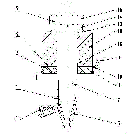
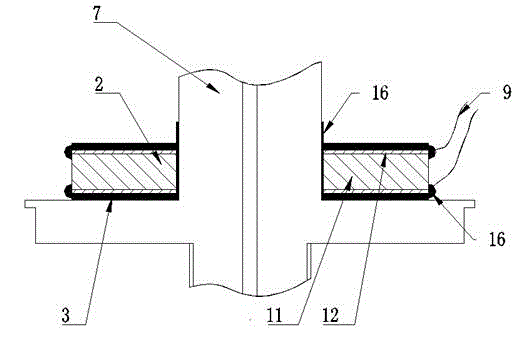
[0021] Such as figure 1 , figure 2 As shown, an ultrasonic-pneumatic spray head includes a spray rod with a small liquid flow channel processed on the axis, an ultrasonic generating device, and a nozzle air nozzle. The middle of the spray rod is provided with a support device with a disc-shaped circular platform structure, and the ultrasonic generating device is sheathed On the spray bar, the ultrasonic generating device is located on the side of the supporting device away from the spray head. The fastening device is used to press and fix the ultrasonic generating device on the supporting device. The nozzle air nozzle is set to surround the spray head at the end of the spray bar. There are piezoelectric chips, back seats and wires. The wires are connected to the piezoelectric chips. The wires are insulated wires. After the piezoelectric chips are introduced, the exposed parts are sealed with insulating glue. The back seat is located at one end of the piezoelectric wafer in contact with the fastening device. The piezoelectric wafer is provided with a piezoelectric ceramic sheet and an electrode sheet. The electrode sheet uses metallic silver as a conductive material to be plated on both sides of the piezoelectric ceramic sheet. After energizing, a short voltage pulse will act on the two poles of the piezoelectric chip through the wire. Due to the back pressure effect, the piezoelectric chip will undergo elastic deformation and produce elastic oscillation.
[0022] The central part of the ultrasonic generating device is provided with a through hole adapted to the boom. The piezoelectric wafer of the ultrasonic generating device is equipped with insulating rubber pads in the contact part of the back seat and the boom, and the part on the wall of the boom corresponding to the piezoelectric chip Apply insulating glue evenly. The piezoelectric ceramic sheet has a planar disc structure, and the piezoelectric ceramic sheet and the central part of the rear seat are provided with a through hole adapted to the spray rod. The nozzle air nozzle is threaded with the nozzle rod, and the inner joint of the nozzle nozzle 6 is machined with fine internal threads. The connection with the fine thread on the nozzle rod 7 plays a role of sealing. The nozzle air nozzle 6 can be adjusted by rotating the nozzle air nozzle. The gap of the spray rod 7. The nozzle 6 of the nozzle is provided with a gas volume regulating valve 4, which adopts a solenoid valve. The opening of the gas volume regulating valve 4 is controlled through an external circuit, the pressure of the external gas supply device is adjusted, and the pressure of the gas is changed to adjust the ventilation volume.
[0023] The fastening device includes a washer, a spring washer and a fixing nut. The end of the spray rod away from the nozzle is provided with a thread. The washer, the spring washer, and the fixing nut are sequentially arranged at the end of the spray rod and fastened by the fixing nut. On the back seat of the ultrasonic generating device, under the premise of ensuring the tightness, an appropriate degree of tightness is required to adapt to the normal operation of the ultrasonic generating device. The gasket, spring washer and fixing nut are made of stainless steel. The nozzle air nozzle, spray rod and rear seat are all made of LY12 aluminum alloy.
[0024] The ultrasonic generating device realizes ultrasonic generation through the back pressure effect of piezoelectric ceramics. When power is applied, short voltage pulses will act on the two poles of the piezoelectric wafer through wires, and the wafer will undergo elastic deformation and generate elastic oscillation. The required ultrasonic waves can be obtained by selecting the appropriate thickness of the piezoelectric ceramics.
[0025] An ultrasonic-pneumatic sprinkler head. Electric current is passed into the ultrasonic generating device, and the ultrasonic generating device will generate an ultra-high frequency vibration. The effect of this vibration will act on the middle boom and produce the maximum amplitude at the top of the middle boom Of oscillation. The air flow from the external air supply device into the nozzle of the nozzle is combined with the liquid flow to the top of the middle spray rod. The liquid flow will be simultaneously affected by the ultrasonic oscillation of the middle nozzle and the impact of the air jet from the nozzle of the nozzle. A large degree of atomization and spraying at a speed close to the injecting airflow, better spreading to the crop area and attaching to the crop. The degree of atomization of droplets and the spraying speed of droplets can be adjusted by adjusting the rotation depth of the nozzle nozzle on the middle spray rod and adjusting the air volume adjustment valve.

PUM

no PUM

Description & Claims & Application Information

We can also present the details of the Description, Claims and Application information to help users get a comprehensive understanding of the technical details of the patent, such as background art, summary of invention, brief description of drawings, description of embodiments, and other original content. On the other hand, users can also determine the specific scope of protection of the technology through the list of claims; as well as understand the changes in the life cycle of the technology with the presentation of the patent timeline. Login to view more.

Similar technology patents

Metal powder pre-pressing device and method for polycrystalline diamond wire-drawing die bushing

ActiveCN104708002AStrong adaptability of processing technologySimple and reasonable structure
Owner:北京迪蒙吉意超硬材料技术有限公司

Classification and recommendation of technical efficacy words

Why Eureka
Try Eureka