Check patentability & draft patents in minutes with Patsnap Eureka AI!

Cam-connecting rod mechanism for cutter

A technology of cam linkage and cutting machine, which is applied in the field of cam linkage mechanism and can solve the problems of low work efficiency, complex structure, and high price

Active Publication Date: 2015-04-29
重庆新锐科技服务有限公司
View PDF6 Cites 3 Cited by
  • Summary
  • Abstract
  • Description
  • Claims
  • Application Information

AI Technical Summary

Problems solved by technology

Due to the complex circuit devices and control devices involved in the existing cutting equipment, the overall internal structure of the equipment is complicated and expensive, and because the cutting equipment lacks a suitable transmission mechanism, the operation of the steel cutting equipment is cumbersome and the work efficiency is not high.

Method used


Image

  • Cam-connecting rod mechanism for cutter

Examples


Embodiment Construction

[0010] Below in conjunction with accompanying drawing and specific embodiment the present invention will be described in further detail:

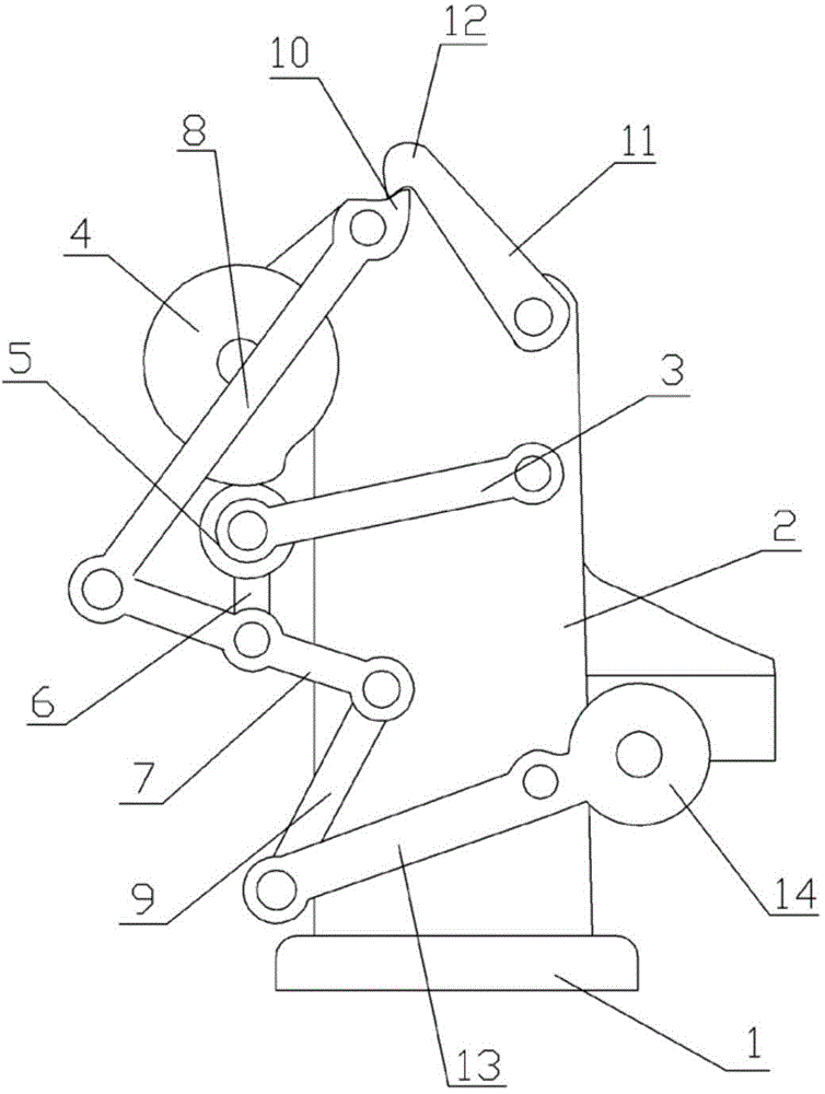
[0011] The reference signs in the accompanying drawings of the description include: base 1, frame 2, rocker 3, cam 4, roller 5, connecting rod 6, first lever 7, second lever 8, third lever 9, arc-shaped protrusion 10, a cross bar 11, a clamping part 12, a rotating shaft 13, and a cutting knife 14.

[0012] Such as figure 1 As shown, the cam linkage mechanism for cutting machine includes a base 1 and a frame 2 arranged on the base 1. The frame 2 is provided with a rocker 3 and a cam 4 connected to the motor, and one end of the rocker 3 is hinged on the On the frame 2, the other end of the rocking bar 3 is provided with a roller 5, the roller 5 adopts a ball-shaped roller, the roller 5 is in contact with the outer surface of the cam 4, and the roller 5 is hinged with a first lever 7 through a connecting rod 6, and is connected Rod 6 is hing...


PUM


Abstract

The invention discloses a cam-connecting rod mechanism for a cutter. The cam-connecting rod mechanism comprises a base and a rack arranged on the base, wherein a rocker and a cam connected with a motor are arranged on the rack; one end of the rocker is hinged to the rack, and a roller is arranged at the other end of the rocker, and forms contact with the outer surface of the cam in an attachment manner; a first lever is hinged to the roller through a connecting rod; a second lever is hinged to one end of the first lever; a third lever is hinged to the other end of the first lever; the second lever is hinged to the rack; a cambered bump is arranged on the second lever; a cross rod is hinged to the rack; a hook-shaped clamping part is arranged on the cross rod, and is pressed against the cambered bump of the second lever; a rotating shaft for fixing a cutting tool is hinged to the third lever, and is hinged to the rack. The cam-connecting rod mechanism for the cutter is simple in structure, convenient to operate and high in working efficiency.

Description

technical field [0001] The cutting device for building materials of the present invention particularly relates to a cam linkage mechanism for a cutting machine. Background technique [0002] A steel bar cutter is a tool used to cut steel bars. Generally, there are fully automatic steel bar cutting machines and semi-automatic steel bar cutting machines. It is one of the necessary equipment for steel bar processing, and it is mainly used for cutting steel bars to fixed length in housing construction, bridges, tunnels, power stations, large-scale water conservancy and other projects. Compared with other cutting equipment, the steel bar cutting machine has the characteristics of light weight, low energy consumption, reliable operation and high efficiency. Therefore, it has been widely used in mechanical processing and small rolling mills in recent years, and has played an important role in various fields of national economic construction. role. The existing cutting equipment ...

Claims


Application Information

Patent Timeline
Patent Type & Authority Applications(China)
IPC IPC(8): B21F11/00
CPCB21F11/00
Inventor 王璇
Owner 重庆新锐科技服务有限公司
Features
  • R&D
  • Intellectual Property
  • Life Sciences
  • Materials
  • Tech Scout
  • Unparalleled Data Quality
  • Higher Quality Content
  • 60% Fewer Hallucinations
Learn More