Air floatation bearing and air floatation high-speed high-photoelectric main shaft

An air bearing and bearing technology, which is applied to bearings, shafts and bearings, large fixed members, etc., can solve problems such as insufficient radial load, and achieve the effects of improving radial load, improving machining accuracy and improving machining efficiency.

Inactive Publication Date: 2015-04-29
东莞市科隆电机有限公司
View PDF8 Cites 16 Cited by
  • Summary
  • Abstract
  • Description
  • Claims
  • Application Information

AI Technical Summary

Problems solved by technology

[0005] The technical problem to be solved by the present invention is to provide an air bearing and an air-floating high-speed high-electric spindle

Method used


Image

  • Air floatation bearing and air floatation high-speed high-photoelectric main shaft
  • Air floatation bearing and air floatation high-speed high-photoelectric main shaft
  • Air floatation bearing and air floatation high-speed high-photoelectric main shaft

Examples


Embodiment Construction

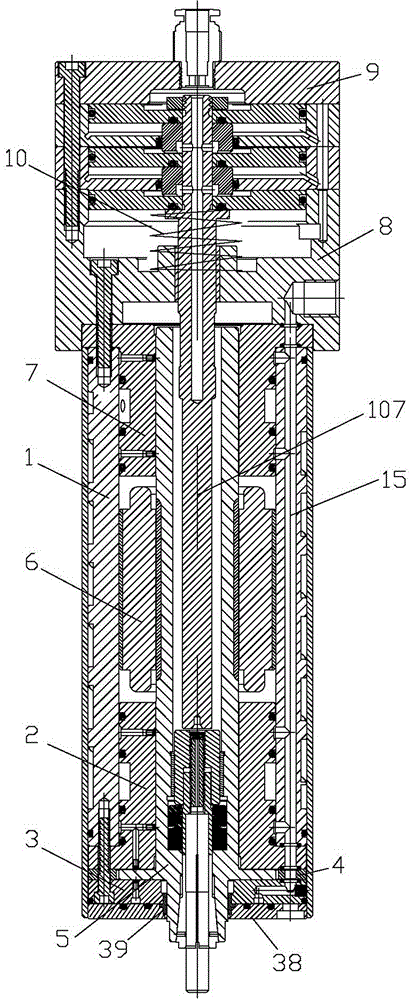
[0047] The specific implementation manners of the present invention will be described below in conjunction with the accompanying drawings.

[0048] Before the specific introduction, let’s explain the front and back mentioned in the technical scheme and implementation of the present application, take the end of the rotor mounting chuck as the front end, and the end far away from the rotor mounting chuck as the rear end, and refer to the front and rear .

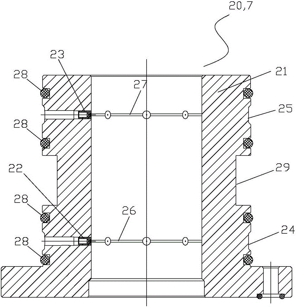
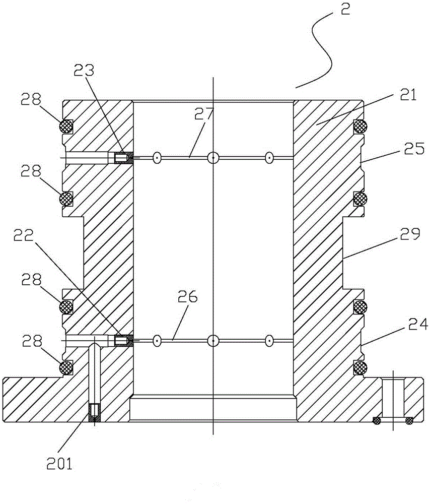
[0049] like figure 1 As shown, an air bearing 20 includes a cylindrical bearing body 21 with no bottom at both ends. The front and rear radial nozzles 22 and rear radial nozzles 23 are respectively equipped at the front and rear ends of the bearing body 21. The front diameter The radial nozzle 22 and the rear end radial nozzle 23 are arranged radially and form inner and outer ends, the outer end is close to the outer wall, and the inner end is close to the inner wall;

[0050] The outer walls of the front and rear ends of th...


PUM


Abstract

The invention discloses an air floatation bearing and an air floatation high-speed high-photoelectric main shaft, and relates to an electric main shaft for machining. According to the air floatation bearing, a front end inner ring-shaped communicated groove and a rear end inner ring-shaped communicated groove are respectively formed in the inner walls of the front end and the rear end of a bearing main body, wherein the front end inner ring-shaped communicated groove corresponds to the inner end of a rear end radial nozzle in position and the front end inner ring-shaped communicated grove is communicated with the rear end radial nozzle from the inner end so as to increase the radial load; and a water way ring groove for heat dissipation and cooling is formed between a front end ring-shaped communicated groove and a rear end ring-shaped communicated groove in the outer wall of the bearing main body. The air floatation high-speed high-photoelectric main shaft comprises a shaft body, a front air floatation bearing, a rear air floatation bearing, a stator, a rotor, a thrust bearing, an ejector rod, a water way/gas way component and a cylinder component. The rotating speed of the electric main shaft provided by the invention exceeds 80000rpm, so that the requirement on the milling rotating speed of the high-photoelectric main shaft is met, and the surface luminance and flatness of a processed product are further ensured.

Description

technical field [0001] The invention relates to an electric spindle for machining, in particular to an air-floating bearing and an air-floating high-speed high-photoelectric spindle. The high photoelectric spindle mentioned in this application refers to an electric spindle that performs high-gloss milling under high-speed rotation, and can form high brightness and high flatness on the surface of the processed parts. Background technique [0002] The traditional high photoelectric spindle is a high photoelectric spindle using ball bearings, which often has precision problems such as large vibration and poor dynamic deflection, which are caused by the characteristics of the ball bearing itself. Although the high-quality photoelectric spindle with ball bearings has a good radial load, the ball bearings are lubricated in the form of contact rolling friction, which will increase the amount of vibration and correspondingly increase the runout value of the dynamic deflection, which...

Claims


Application Information

Patent Timeline
Patent Type & Authority Applications(China)
IPC IPC(8): B23B19/02F16C32/06
CPCB23Q1/70F16C32/0614
Inventor 陈文生
Owner 东莞市科隆电机有限公司
Why Eureka
Try Eureka