Deburring machine

A technology for stab removal machine and fuselage, which is applied in the field of chain production, which can solve problems such as the shaking of the stab removal mechanism, oil leakage and failure of the oil cylinder, and achieve good clamping effect, accurate positioning and good stability

Inactive Publication Date: 2015-04-29
江苏金茂制链有限公司
View PDF15 Cites 3 Cited by
  • Summary
  • Abstract
  • Description
  • Claims
  • Application Information

AI Technical Summary

Problems solved by technology

There are generally two destab oil cylinders in the destab mechanism. Because it is impossible to synchronize, the sliding frame will deviate sideways during the destab process, which will cause impacts on its adjacent parts, thereby slowly loosening some screws and causing The entire destab mechanism shakes, resulting in unstable positioning or failure of some actions; the structure of the movable clamping arm of the clamping mechanism and the relative position connected with the clamping cylinder determine that the mechanism is the most problematic in the destab machine. If there is a deviation in actual use, it is easy to cause damage to the workpiece; the feed cylinder and the tool seat of the tool feed mechanism are generally threaded. This connection method has a disadvantage. If the tool seat processing or assembly clearance Large, or the relevant parts are worn out during work, which will cause the gap between the moving parts of the mechanism to increase. The most direct consequence is that the piston rod of the feed cylinder will be subjected to lateral force, resulting in oil leakage from the cylinder.

Method used


Image

  • Deburring machine
  • Deburring machine
  • Deburring machine

Examples


Embodiment Construction

[0018] The present invention is described in further detail now in conjunction with accompanying drawing. These drawings are all simplified schematic diagrams, which only illustrate the basic structure of the present invention in a schematic manner, so they only show the configurations related to the present invention.

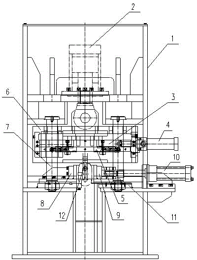
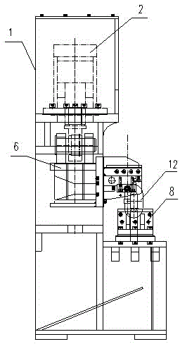
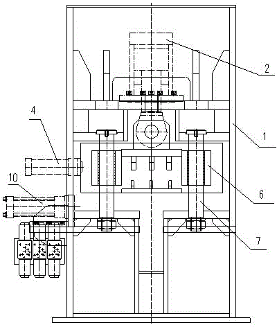
[0019] Such as Figure 1-3 As shown, a stab removal machine includes a body 1 and a clamping mechanism, a stab removal mechanism and a knife feeding mechanism arranged on the body 1 .

[0020] The clamping mechanism includes a clamping oil cylinder 10, a movable clamping arm 9 and a fixed clamping seat 8, the fixed clamping seat 8 is fixed on the fuselage 1, and the movable clamping arm 9 is correspondingly arranged on the fixed clamping seat 8. On one side of the seat 8, the clamping cylinder 10 is connected with the movable clamping arm 9, and the clamping cylinder 10 drives the movable clamping arm 9 to move left and right. The movable clamping arm 9 is a...


PUM


Abstract

The invention relates to a deburring machine which comprises a machine body, a clamping mechanism, a deburring mechanism and a feed mechanism. The clamping mechanism comprises a clamping oil cylinder, a movable clamping arm and a fixing clamping seat, wherein the fixing clamping seat is fixed to the machine body, and the clamping oil cylinder is connected with the movable clamping arm and drives the movable clamping arm to perform left-right movement. The deburring mechanism comprises a deburring oil cylinder, guide columns and a sliding frame, wherein the guide columns are symmetrically fixed to two sides of the machine body, the sliding frame is arranged on the guide columns, the deburring oil cylinder drives the sliding frame to vertically slide along the guide columns, the feed mechanism is arranged on the sliding frame and comprises a feed oil cylinder, a cutter rest and a deburring cutter, the deburring cutter is fixed to the cutter rest, the cutter rest is connected with the feed oil cylinder, and the feed oil cylinder drives the cutter seat to perform left-right movement. The deburring machine clamps a workpiece through the clamping mechanism, is accurate in positioning and good in clamping effect and stability, performs deburring through the deburring mechanism and the feed mechanism, no oil leakage phenomenon does not occur, and the quality of obtained products are high.

Description

technical field [0001] The invention relates to the field of chain production, in particular to a deburring machine for removing burrs on chain links. Background technique [0002] Existing link destackers generally include a clamping mechanism, a destacker mechanism and a knife feed mechanism. There are generally two destab oil cylinders in the destab mechanism. Because it is impossible to synchronize, the sliding frame will deviate sideways during the destab process, which will cause impacts on its adjacent parts, thereby slowly loosening some screws and causing The entire destab mechanism shakes, resulting in unstable positioning or failure of some actions; the structure of the movable clamping arm of the clamping mechanism and the relative position connected with the clamping cylinder determine that the mechanism is the most problematic in the destab machine. If there is a deviation in actual use, it is easy to cause damage to the workpiece; the feed cylinder and the to...

Claims


Application Information

Patent Timeline
Patent Type & Authority Applications(China)
IPC IPC(8): B23D79/00
Inventor 董庆春束建平
Owner 江苏金茂制链有限公司
Why Eureka
Try Eureka