Marking method based on controllable distance indication and 3D (three-dimensional) laser marking machine

A laser marking machine, 3D technology, applied in typewriters, laser welding equipment, printing and other directions, can solve the problems of distortion of marking patterns, lack of positioning structure, and difficulty for technicians to accurately place and adjust the height of marking objects. Achieve the effect of improving focusing efficiency, simple structure and low cost

Active Publication Date: 2015-04-29
GUANGZHOU NEW CKLASER CO LTD
View PDF6 Cites 15 Cited by
  • Summary
  • Abstract
  • Description
  • Claims
  • Application Information

AI Technical Summary

Problems solved by technology

However, without a positioning structure, it is difficult for technicians to accurately place and adjust the position and height of the marking object, and 3D surface marking requires very high precision. As long as there is a deviation in the position or height of the marking object, it is likely to cause the entire Distortion of marking pattern
In addition, due to the complexity of the surface of the 3D marking object, the requirements for setting the reference point are flexible and variable, so the traditional fixed focus system has been unable to meet the requirements of 3D laser marking

Method used


Image

  • Marking method based on controllable distance indication and 3D (three-dimensional) laser marking machine
  • Marking method based on controllable distance indication and 3D (three-dimensional) laser marking machine
  • Marking method based on controllable distance indication and 3D (three-dimensional) laser marking machine

Examples


Embodiment 1

[0077] This embodiment corresponds to the above-mentioned second and third principles, that is, the situation of using two reflective mirrors to deflect light, see Figure 5 to Figure 10 , the laser marking machine of the present invention comprises a cabinet 9, a reference plate 7 arranged on the cabinet 9, a control unit 8 arranged on the cabinet 9, a lifting frame 6 vertically arranged on the reference plate 7, a marking head 5, and a lift A rotating handle 61 is provided on the top of the frame 6, and the marking head 5 is arranged on the elevating frame 6. The height of the marking head 5 can be adjusted by rotating the rotating handle 61. This is a method of manual adjustment. In the present invention, the control unit 8 can also Automatically adjust the lifting frame 6. When the height difference of the marking object is large (beyond the focal length range of laser marking), the position of the marking head 5 can be adjusted manually or automatically, so that the markin...

Embodiment 2

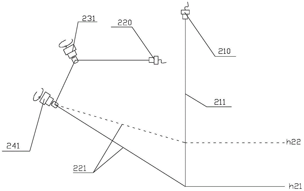
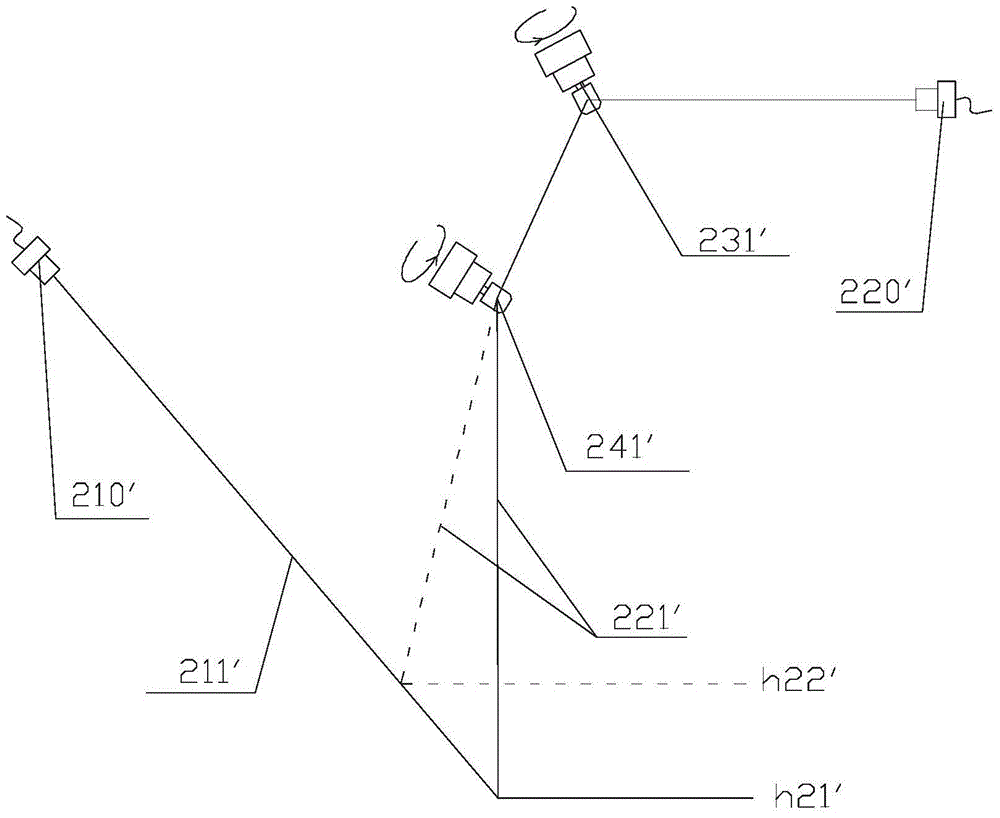
[0086] See attached Figure 11 , the laser in this embodiment, the second visible light beam 321 emitted by the second visible light indicator 320, the reflection device (including the first mirror 332 driven and controlled by the first motor 331 and the second mirror 332 driven and controlled by the second motor 341 Reflector 342) is the same as Embodiment 1, the difference is that the front housing of this embodiment is also provided with an adjusting device (the third reflector 352 driven and controlled by the third motor 351), and the first visible light indicator 310 emits The first visible light beam 311 is emitted, and the first visible light beam 311 encounters the third reflective mirror 352 during transmission, and the first visible light beam 311 intersects with the second visible light beam 321 after being reflected by the third reflective mirror 352, and the intersection point is For the optimal working point of laser marking, the function of the added adjustment ...

Embodiment 3

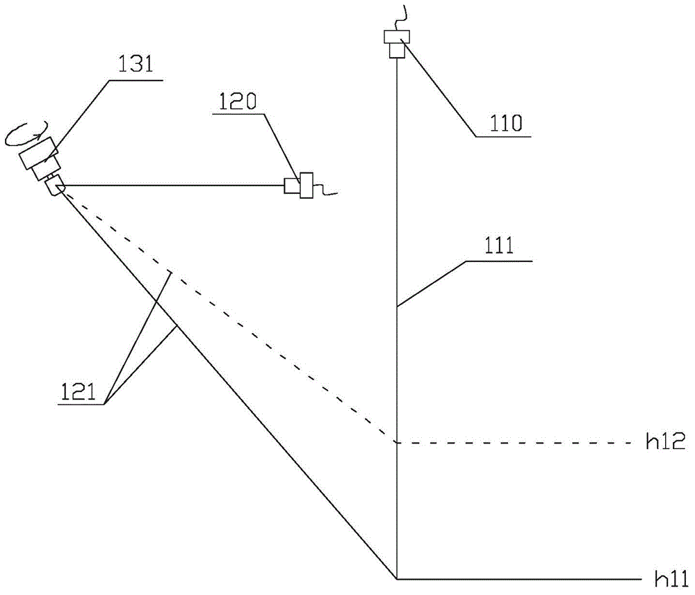
[0088] See attached Figure 12 , what this embodiment applies is the first principle, that is, the second visible light beam 121 is only reflected once, the reflection device in this embodiment is different from Embodiment 1, and the reflection device in this embodiment is driven by the first motor deflection of the first mirror 132 .

[0089]The first visible light indicator 110 in this embodiment and the first visible light indicator 210 in Embodiment 1 can be mounted on the front case in the same manner, and the first visible light emitted by the first visible light indicator 110 in this embodiment The light beam 111 is a downward fixed light, and the first reflector 132 controls the deflection of the second visible light beam 121 through the first motor 131 to achieve the effect of changing the height of the intersection point; the structure of this embodiment is simple and the cost is low. A reflective lens, but the requirements for installation are relatively high, sinc...


PUM

PropertyMeasurementUnit
wavelengthaaaaaaaaaa

Abstract

The invention discloses a marking method based on controllable distance indication and a 3D (three-dimensional) laser marking machine using the method. The 3D laser marking machine comprises a first visible light indicator, a second visible light indicator and a control unit, wherein the first visible light indicator can emit a first visible light beam to a marking area, a reflecting device is arranged on a light path of the second visible light indicator, and is used for reflecting a second visible light beam, the second visible light beam is reflected and is crossed with the first visible light beam in the marking area, the controlling unit is used for controlling the deflecting angle of the reflecting device, and the crossing point of the first light beam and the second light beam corresponds to an initial focus point of the 3D laser marking machine. The 3D laser marking machine has the advantage that the initial focus distance of the laser marking can be displayed through controlling the crossing of the visible light beams, and the 3D laser marking machine can automatically focus, so the indication of the initial focus distance can be accurately and quickly completed.

Description

technical field [0001] The invention relates to the field of laser marking, in particular to a marking method for laser marking on a three-dimensional surface of an object and a controllable distance indication marking method and a 3D laser marking machine applying the method. Background technique [0002] Laser marking machine (laser marking machine) is a technology that uses laser beams to permanently mark the surface of a material. This technology generates a laser beam through a laser, undergoes a series of optical transmission and processing, and finally focuses the beam through an optical lens, and then deflects the focused high-energy beam to a designated position on the surface of the object to be processed. Laser marking machines can mark various characters, symbols and patterns, and have broad market application prospects. [0003] Traditional laser marking machines only mark on two-dimensional planes. During marking, since the laser beam is invisible, in order t...

Claims


Application Information

Patent Timeline
Patent Type & Authority Applications(China)
IPC IPC(8): B23K26/36B23K26/04
CPCB23K26/04B23K26/361B41J2/435B41J2/451B41J3/407
Inventor 徐强
Owner GUANGZHOU NEW CKLASER CO LTD
Why Eureka
Try Eureka