Self-locking tool

A self-locking and cutting tool technology, applied in the direction of cutting tools for lathes, cutting tools for shearing machines, positioning devices, etc., can solve the problems of insufficient flexibility and firmness of tool fixing and locking, complex and inaccurate movement and positioning, etc.

Inactive Publication Date: 2015-04-29
常州市海伦工具有限公司
View PDF0 Cites 5 Cited by
  • Summary
  • Abstract
  • Description
  • Claims
  • Application Information

AI Technical Summary

Problems solved by technology

The current tool control methods are various, but most of them have problems such as not flexible enough to fix and lock the tool, complicated and imprecise moving and positioning

Method used


Image

  • Self-locking tool

Examples


Embodiment Construction

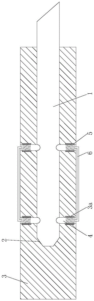
[0011] The present invention will be further described in detail below in conjunction with the accompanying drawings and specific embodiments.

[0012] refer to figure 1 , The self-locking tool of the present invention includes a tool body 1, the peripheral surface of one end of the tool body 1 is a conical surface 2, and a spherical groove is provided on the peripheral surface of the tool body 1. It also includes a knife handle 3, which is provided with an axial center hole, and the outer circumference of the knife handle is provided with a radial hole 3a penetrating through the center hole, and the radial hole is small at both ends and large in the middle. The step hole is slidably matched with a positioning pin 4 and a spring 5 in the radial hole. The spring 5 is sleeved on the positioning pin 4. The inner ring of the spring 5 is fixedly connected with the circumferential surface of the positioning pin 4. The two parts of the spring 5 pass through the steps respectively. T...


PUM


Abstract

The invention relates to a self-locking tool which comprises a tool body. The circumferential surface at one end of the tool body is a conical surface. The circumferential surface of the tool body is provided with spherical grooves. The self-locking tool further comprises a tool handle. The tool handle is provided with an axial central hole. Radial holes penetrating to the central hole are formed in the outer periphery of the tool handle. Each radial hole is a stepped hole with two small ends and one large middle. A positioning pin and a spring are slidably fitted in each radial hole. Each spring sleeves the corresponding positioning pin. The inner ring of each spring is fixedly connected with the circumferential surface of the corresponding positioning pin. Two ends of each spring are limited by the two stepped faces of the corresponding stepped hole. The end, facing the central hole, of each positioning hole is a ball head. After the tool body is inserted into the central hole, the ball heads of the positioning pins are inserted into the spherical grooves of the tool body. The self-locking tool has the advantage that the tool can be positioned and locked quite conveniently.

Description

technical field [0001] The invention relates to a self-locking tool. Background technique [0002] Machining is a process of changing the shape or performance of workpieces with processing machinery. According to the temperature state of the processed workpiece, it can be divided into cold processing and hot processing. Generally, processing at room temperature does not cause chemical changes or phase changes of the workpiece, which is called cold processing. Cold processing can be divided into cutting processing and pressure processing according to the difference in processing methods. The cutting process mentioned here is to use a specific tool to cut the workpiece and process it into a specific shape. In the cutting process, the control of the tool becomes the key point of the processing technology. The current tool control methods are various, but most of them have the problems of not being flexible enough to fix and lock the tool, complex and imprecise moving and po...

Claims


Application Information

Patent Timeline
Patent Type & Authority Applications(China)
IPC IPC(8): B23Q3/00B23D35/00B23B27/00
CPCB23B31/005
Inventor 曹大龙
Owner 常州市海伦工具有限公司
Why Eureka
Try Eureka