
Adjustable and indexable quick positioning and clamping device for machining aviation shell part

A technology for positioning and clamping and housing, applied in positioning devices, metal processing machinery parts, metal processing equipment, etc., can solve the problems of poor economic benefits, difficult clamping, and time-consuming, reducing wear and improving production. Efficiency, effect of improving mutual positional relationship and machining accuracy

Inactive Publication Date: 2016-06-08
HENAN POLYTECHNIC UNIV
View PDF14 Cites 4 Cited by
  • Summary
  • Abstract
  • Description
  • Claims
  • Application Information

AI Technical Summary

Problems solved by technology

[0002] With the development of numerical control technology, the shapes of aerospace shell parts are becoming more and more diverse and complex, and the requirements for position accuracy and dimensional accuracy are getting higher and higher, but the positioning of shell parts is intensified. It has become a bottleneck problem that restricts parts from obtaining high precision and high efficiency. Generally, shell parts, especially aviation shell parts, have a special shape and structure, and it is difficult to clamp. If conventional fixtures such as three-jaw chucks and four-jaw chucks are used Clamping such as discs cannot be completed, and it takes a lot of time to find the alignment, and the economic benefit is not good

Method used


Image

  • Adjustable and indexable quick positioning and clamping device for machining aviation shell part
  • Adjustable and indexable quick positioning and clamping device for machining aviation shell part
  • Adjustable and indexable quick positioning and clamping device for machining aviation shell part

Examples


Embodiment 1

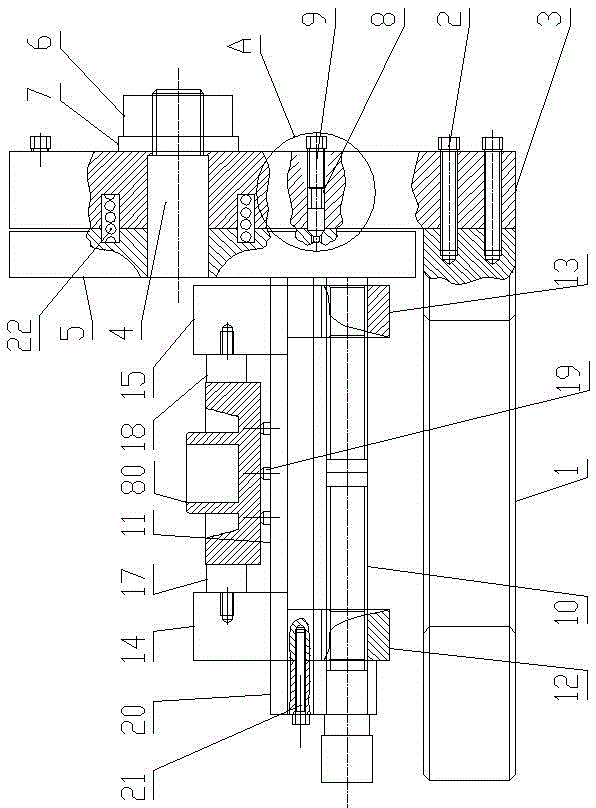
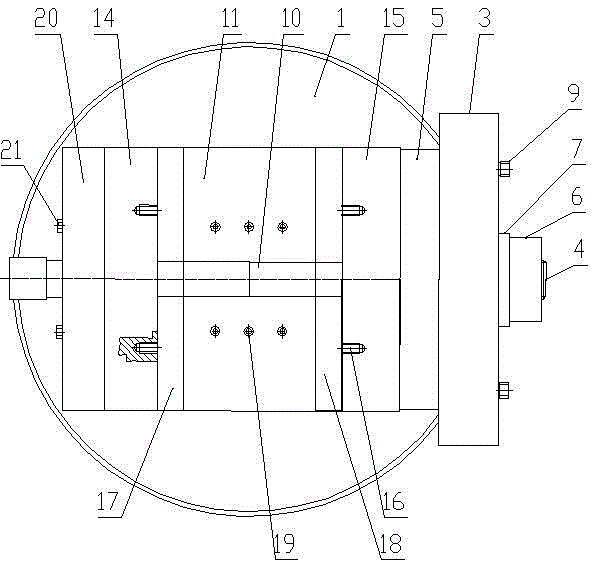
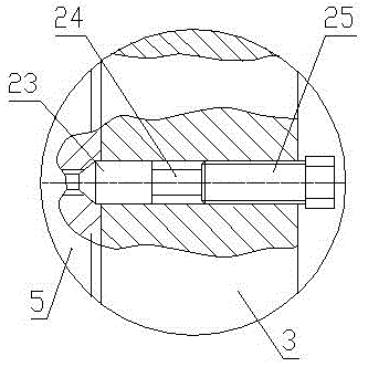
[0024] Embodiment one: if figure 1 , figure 2 , image 3 and Figure 4 As shown, the adjustable and indexable fast positioning clamping device for processing aviation shell parts of the present invention includes a horizontally arranged bottom plate 1, and the right side of the bottom plate 1 is vertically provided with a support plate 3 through fastening bolts 2 to support A rotating shaft 4 is horizontally arranged on the plate 3, and the left end of the rotating shaft 4 is fixedly connected with a mounting plate 5. The mounting plate 5 is located on the left side of the supporting plate 3 and is parallel to the supporting plate 3. The right end of the rotating shaft 4 is threaded with a fastening nut 6, and the fastening nut 6 Through the washer 7 sleeved on the rotating shaft 4, press fit with the right side of the support plate 3;

[0025] The support plate 3 is provided with threaded holes 8 respectively located above, below, in front of, and behind the rotating shaf...

Embodiment 2

[0031] Embodiment two: if Figure 5 As shown, the difference from Embodiment 1 is that both the left clamping block 17 and the right clamping block 18 are formed by bending steel plates.


PUM


Abstract

An adjustable and indexable quick positioning and clamping device for machining an aviation shell part comprises a bottom plate, a support plate, a rotating shaft, an installing disc, a fastening nut, positioning pins, a guide rail, a two-way screw, a left sleeve, a right sleeve, a left slide block, a right slide block, a left clamping block and a right clamping block, and the guide rail is provided with positioning columns which are located on the at the front side and the back side of the two-way screw. The shell part is fixed between the left clamping block and the right clamping block through the positioning columns and clamped tightly by driving the two-way screw, and a fixture body and the shell part are driven by rotation of the rotating shaft to be turned over by 90 degrees to achieve machining of the other face and then turned over by 180 degrees to achieve machining of the third face. According to the adjustable and indexable quick positioning and clamping device for machining the aviation shell part, clamping of the three faces and machining of holes formed in the three faces can be completed for once, the mutual position relation and the machining precision of the holes formed in the shell are improved, quick clamping can be achieved, the production efficiency is greatly improved, and the economic benefit of batch production is especially good.

Description

technical field [0001] The invention belongs to the technical field of mechanical manufacturing and processing, and in particular relates to an adjustable and indexable fast positioning clamping device for processing aviation shell parts. Background technique [0002] With the development of numerical control technology, the shapes of aerospace shell parts are becoming more and more diverse and complex, and the requirements for position accuracy and dimensional accuracy are getting higher and higher, but the positioning of shell parts is intensified. It has become a bottleneck problem that restricts parts from obtaining high precision and high efficiency. Generally, shell parts, especially aviation shell parts, have a special shape and structure, and it is difficult to clamp. If conventional fixtures such as three-jaw chucks and four-jaw chucks are used Clamping such as discs cannot be completed, and it takes a lot of time to find the alignment, and the economic benefit is n...

Claims


Application Information

Patent Timeline
IPC IPC(8): B23Q3/12
CPCB23Q3/12
Inventor 童景琳封志彬张存鹰张伟陈凡王晓博崔峰
Owner HENAN POLYTECHNIC UNIV
Learn More