Magnetic connection structure

Inactive Publication Date: 2015-01-15
XIAMEN RUNNER IND CORP
View PDF7 Cites 5 Cited by
  • Summary
  • Abstract
  • Description
  • Claims
  • Application Information

AI Technical Summary

Benefits of technology

[0014]For the magnetic connection structure of the present invention, the magnetic sleeve body and the plastic fastener are produced by means of ejection-to-mode separately. The magnetic sleeve body is formed by ejection-to-mode using the magnetic iron powder and plastic mixed at a certain ratio; while the plastic fast

Problems solved by technology

Therefore, this kind of structure is rather complicated.
For this type of plastic connection structure, the production steps are numerous and rather difficult, so that the production cost is high.
Moreover, in case a connection piece of magnetic iron

Method used


Image

  • Magnetic connection structure
  • Magnetic connection structure
  • Magnetic connection structure

Examples


Embodiment Construction

[0023]The purpose, construction, features, functions and advantages of the present invention can be appreciated and understood more thoroughly through the following detailed description with reference to the attached drawings.

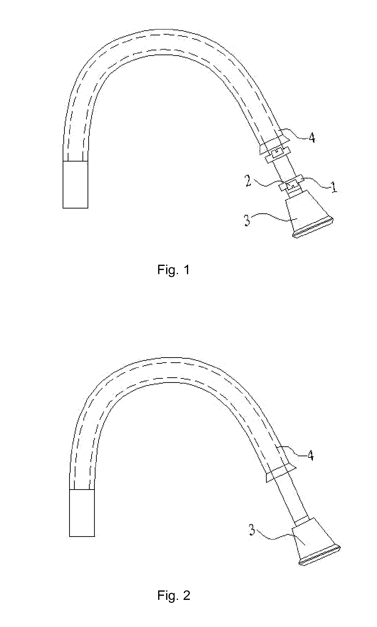
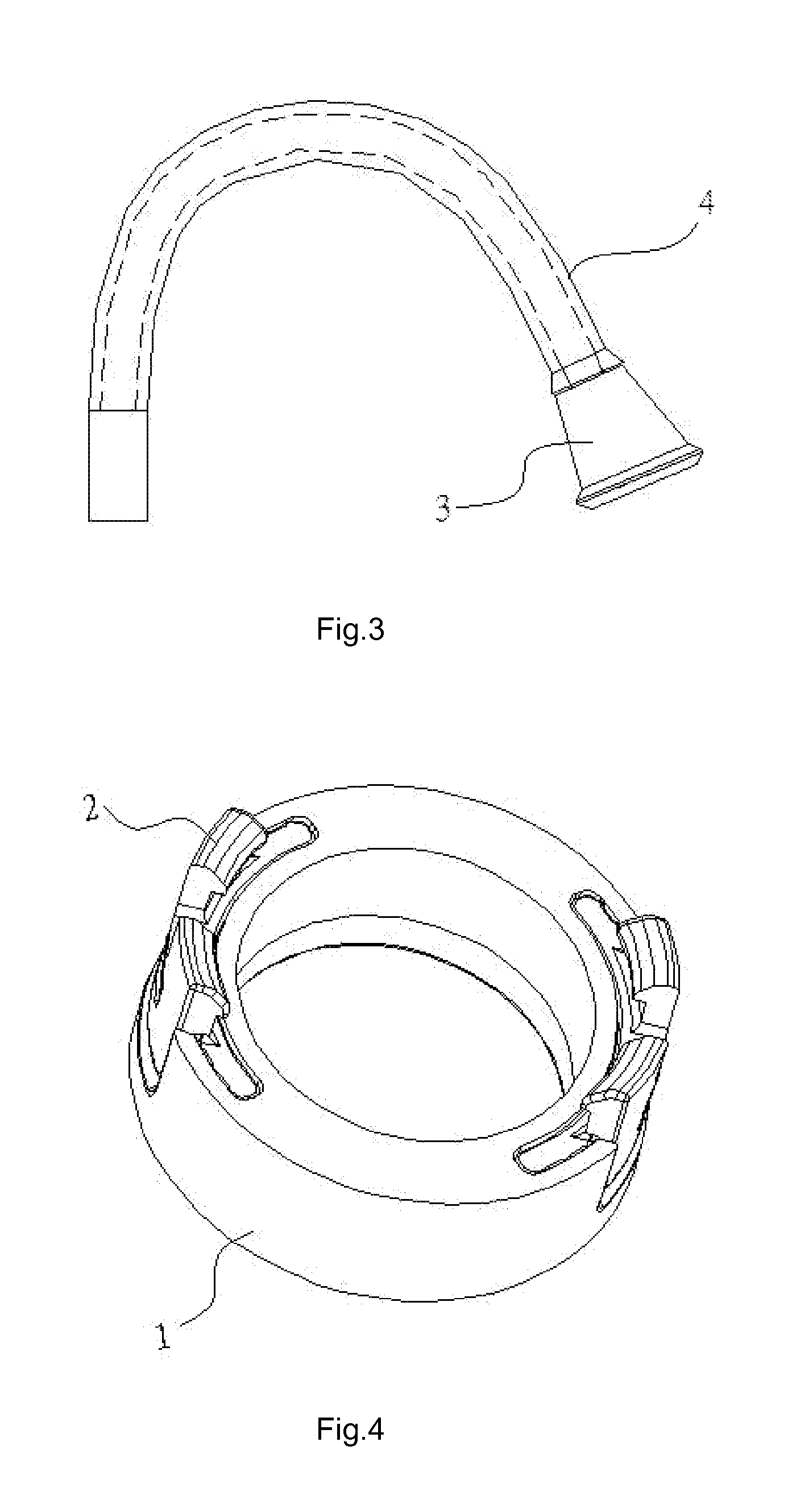
[0024]Refer to FIGS. 1, 2, 3 respectively for an exploded / schematic diagram of a pulling type faucet according to the present invention; a schematic diagram of a pulling type faucet of state 1 to be used as an ejection head according to the present invention; and a schematic diagram of a pulling type faucet of state 2 to be used for fixing a faucet according to the present invention.

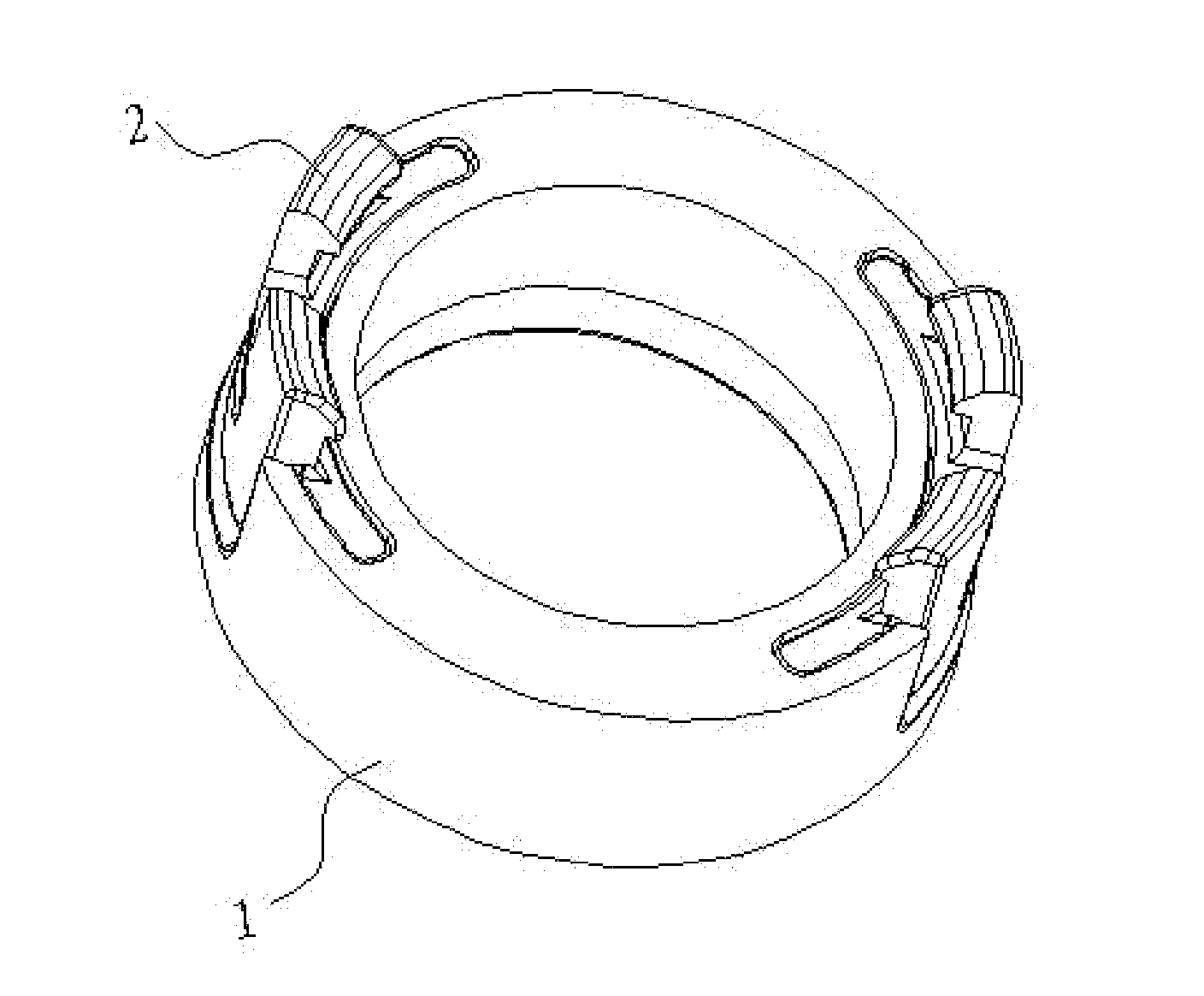
[0025]Also, refer to FIGS. 4, 5, 6 respectively for a perspective / schematic diagram of a magnetic connection structure according to the present invention; a cross section view of a magnetic connection structure according to the present invention; and an exploded / schematic diagram of a magnetic connection structure according to the present invention. As shown in FIGS. 4, 5, 6, the pr...


PUM


Abstract

A magnetic connection structure, includes a ring-shape magnetic sleeve body, made of mixed magnetic iron powder and plastic by means of ejection-to-mode; and a plastic fastener, provided in an arc-shape opening on both sides of the ring-shape magnetic sleeve body, for fastening a faucet seat or an ejection head. In the magnetic connection structure, the magnetic sleeve body and the plastic fastener are formed by means of ejection-to-mode separately. The magnetic sleeve body is formed by ejection-to-mode using magnetic iron powder and plastic mixed at a certain ratio; while the magnetic fastener is formed by means of ejection-to-mode separately. Then, the magnetic sleeve body and the plastic fastener are fastened together, to achieve said magnetic connection structure, that is low in production cost and easy to install. In case the plastic fastener is damaged, it can be replaced readily.

Description

BACKGROUND OF THE INVENTION[0001]1. Field of Invention[0002]The present invention relates to a magnetic connection structure, and in particular to a magnetic connection structure used for a pulling type faucet.[0003]2. The Prior Arts[0004]In general, a conventional faucet is provided with a faucet main body, one or a plurality of water flow control devices, and an ejection tube. The ejection tube is used for ejecting the water flowing through a valve. For this type of faucet, the water ejection is fixed to a single direction; or alternatively, the ejection tube can be rotated, yet it can only rotate within a certain range, so that water ejection is limited to that range.[0005]To improve this structure, the conventional faucet is provided with a separate and distinct ejection head, that can be controlled manually, to provide user with more operation flexibility according to the actuation direction and actuation point of water ejection. In particular, in order to facilitate spraying w...

Claims


Application Information

Patent Timeline
IPC IPC(8): E03C1/04F16L37/00
CPCE03C2001/0414E03C1/0404F16L37/004E03C2001/0415
Inventor CHEN, XI-MINPENG, KE-SHENGLIAO, LI-ZHONG
Owner XIAMEN RUNNER IND CORP
Why Eureka
Try Eureka