
Large-outer-diameter pin clamp

A technology with large outer diameter and pin shaft, applied in the field of mechanical clamping, can solve the problems of pin shaft runout, error, clamping difficulty, etc., and achieve the effect of convenient adjustment

Inactive Publication Date: 2015-04-29
TERRENCE ENERGY
View PDF0 Cites 1 Cited by
  • Summary
  • Abstract
  • Description
  • Claims
  • Application Information

AI Technical Summary

Problems solved by technology

[0002] At present, the fixtures are installed on the milling machine table mainly through the vise and the combined pressing block; however, when processing the pin shaft parts, because the pin shaft parts are relatively smooth, it is difficult to clamp, and it is easy to cause the pin shaft to jump during processing. , resulting in errors; when processing pin shaft parts with larger outer diameters, it is more difficult to clamp

Method used


Image

  • Large-outer-diameter pin clamp
  • Large-outer-diameter pin clamp

Examples


Embodiment 2

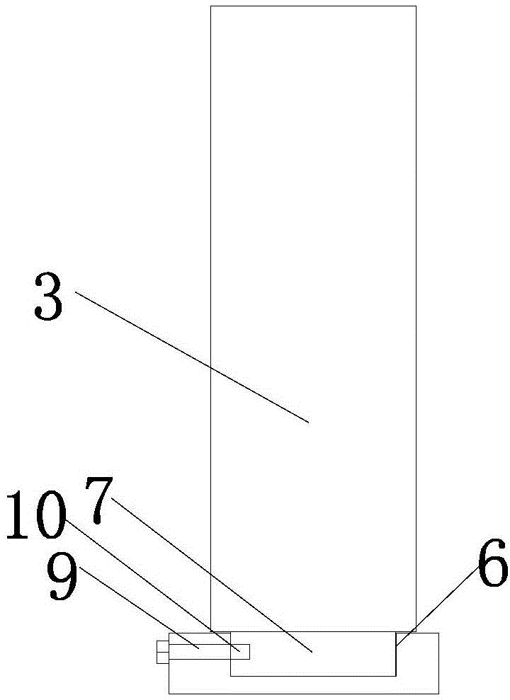
[0016] The side wall of the chute is provided with strip slots 9 along the length direction. By arranging the bar-shaped slots and cooperating with the bolts, when it is necessary to lock the positions of the first and second sliders, it is only necessary to tighten the bolts so that the ends of the bolts are against the first and second sliders.

Embodiment 3

[0018] A first screw hole 10 used in conjunction with a bar-shaped slot is provided on the side wall of the first slide rail. By providing the first screw hole, when it is necessary to lock the positions of the first and second sliders, it is only necessary to screw the screw into the first screw hole, and the screw connection is relatively stable.

Embodiment 4

[0020] A second screw hole used in conjunction with the bar-shaped slot is provided on the side wall of the second slide rail. By providing the second screw hole, when it is necessary to lock the positions of the first and second sliders, it is only necessary to screw the screw into the second screw hole, and the screw connection is relatively stable.


PUM


Abstract

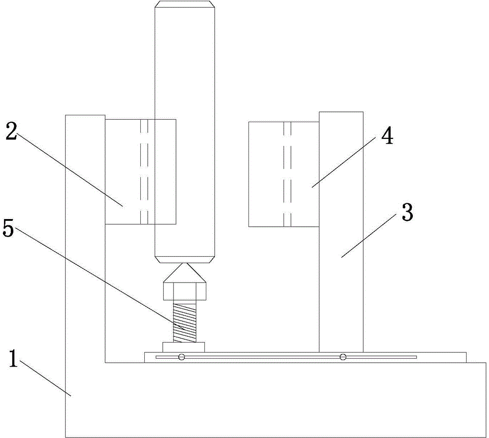
The invention relates to the technical field of mechanical clamping, in particular to a large-outer-diameter pin clamp. A first limit device comprises a first V-shaped limit block arranged on the vertical portion of a support; a second limit device comprises a supporting column, and a second V-shaped limit block is arranged on the supporting column and corresponds to the first V-shaped limit block; a third limit device comprises a support nail arranged on the transverse portion of a base, the nail head of the support nail faces downwards, and the nail point of the support nail faces upwards; a slide groove is arranged among the supporting column, the nail head of the support nail and the transverse portion of the support; a first slide rail matched with the slide groove is arranged on the bottom surface of the support column, and the bottom surface of the nail head of the support nail is provided with a second slide rail cooperatively used with the slide groove. The large-outer-diameter pin clamp can be used for clamping pin parts large in outer diameter and is firm in clamping.

Description

technical field [0001] The invention relates to the technical field of mechanical clamping, in particular to a pin shaft clamp with a large outer diameter. Background technique [0002] At present, the fixtures are installed on the milling machine table mainly through the vise and the combined pressing block; however, when processing the pin shaft parts, because the pin shaft parts are relatively smooth, it is difficult to clamp, and it is easy to cause the pin shaft to jump during processing. , resulting in errors; when processing pin shaft parts with larger outer diameters, it is more difficult to clamp. Contents of the invention [0003] The purpose of the present invention is to provide a pin clamp with a large outer diameter that can clamp a pin with a large outer diameter and firmly hold it. [0004] Technical scheme of the present invention is as follows: [0005] Large outer diameter pin shaft clamp; including an "L" shaped bracket, a first limiting device, a sec...

Claims


Application Information

Patent Timeline
Patent Type & Authority Applications(China)
IPC IPC(8): B23Q3/06
CPCB23Q3/062
Inventor 姚保纯王建忠吴振华史佳
Owner TERRENCE ENERGY
Learn More