Grinding device for outer edges of automobile accessories

A technology for auto parts and outer edge, which is applied in the field of auto parts outer edge grinding device, which can solve the problems of operator's personal safety hazards, waste debris easy to splash out, difficult to clean up, etc., to reduce safety hazards, clean and maintain convenient and efficient , Improve the effect of accuracy and efficiency

Inactive Publication Date: 2015-04-29
CHONGQING DAZU RONGYI MACHINERY PARTS
1 Cites 5 Cited by

AI-Extracted Technical Summary

Problems solved by technology

[0002] Most auto parts are stamped parts, which are integrally formed. After rough machining, there will be many burrs on the circumference of the parts. At this time, the burrs need to be polished to meet the requirements of use; most manufacturers treat the burrs on the circumference of the parts as Manual grinding, so the efficiency is very low;
[0003] The "Grinding Device for the Outer Edge of Auto ...

Abstract

The invention relates to a grinding device for outer edges of automobile accessories. The grinding device comprises a base, a motor, a grinding base, a grinding wheel, a transmission shaft and a grinding guide disc, wherein the motor is fixedly arranged on the inner bottom surface of the base; the grinding base is arranged on the upper end surface of the base; the grinding wheel is arranged at the upper end of the grinding base; the upper end of the transmission shaft is fixedly connected with the grinding wheel, and the transmission shaft can rotationally penetrate through the center of the grinding base and can be connected with an output shaft of the motor through a belt; the grinding guide disc is arranged at the upper end of the grinding base and surrounds the grinding wheel. Compared with the prior art, the grinding device for outer edges of automobile accessories disclosed by the invention is convenient to clean and maintain, capable of eliminating the potential safety hazard of sweeps on people and high in grinding accuracy.

Application Domain

Technology Topic

Image

  • Grinding device for outer edges of automobile accessories
  • Grinding device for outer edges of automobile accessories

Examples

  • Experimental program(1)

Example Embodiment

[0014] The principles and features of the present invention will be described below with reference to the accompanying drawings. The examples cited are only used to explain the present invention and not used to limit the scope of the present invention.
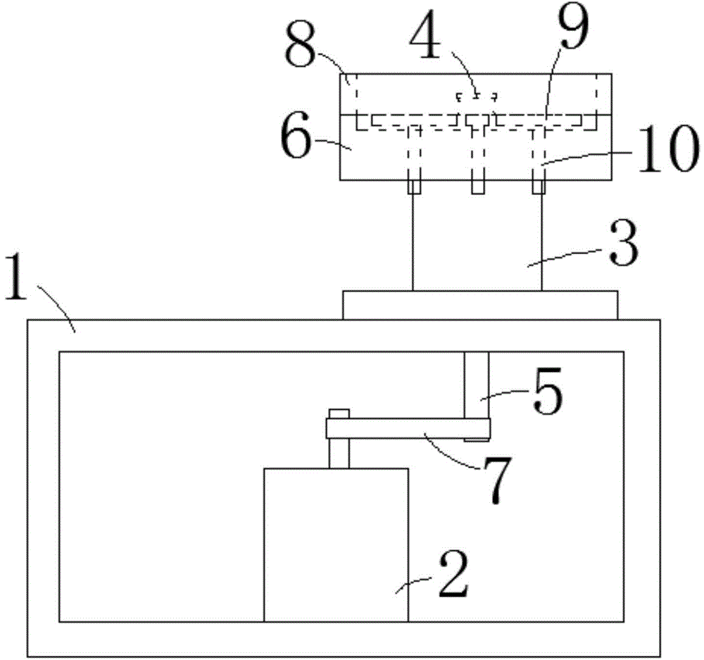
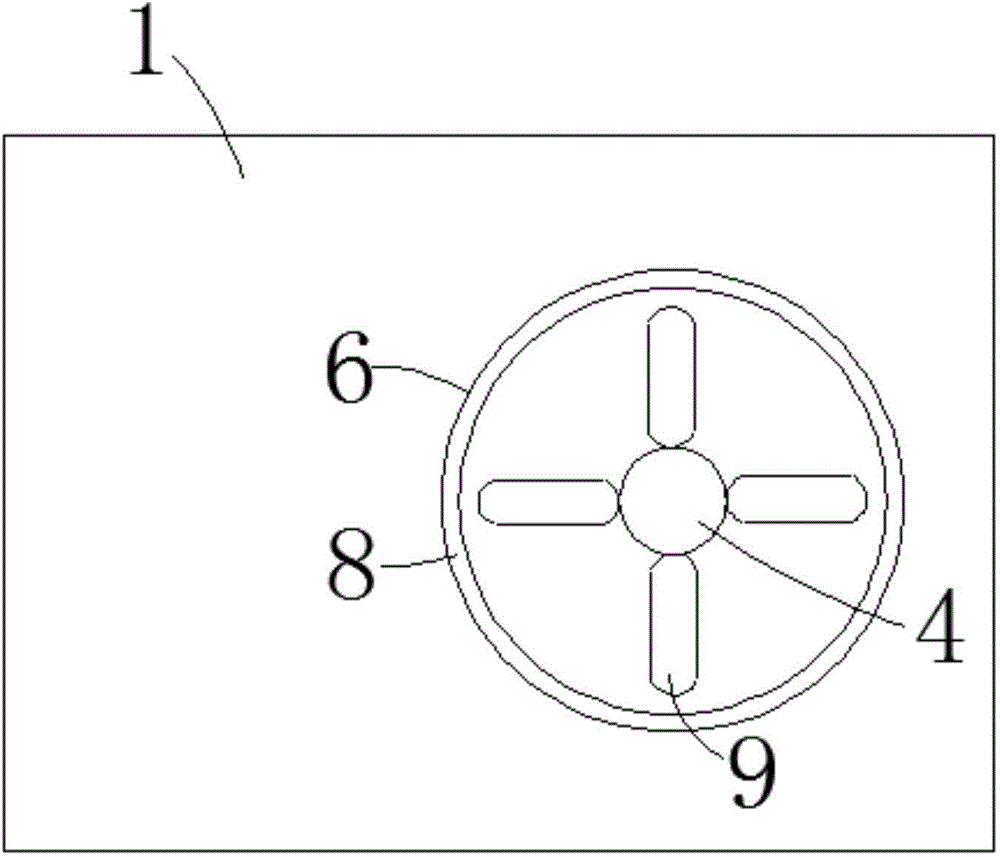
[0015] Such as figure 1 As shown, a grinding device for the outer edge of an automobile part includes a base 1, a motor 2, a grinding base 3, a grinding wheel 4, a transmission shaft 5, and a grinding guide plate 6. The motor 2 is fixed on the inner bottom surface of the base 1 The grinding base 3 is placed on the upper end surface of the base 1, the grinding wheel 4 is placed at the upper end of the grinding base 3, the upper end of the transmission shaft 5 is fixedly connected to the grinding wheel 4, and the The transmission shaft 5 rotatably passes through the center of the polishing base 3, and is linked with the output shaft of the motor 2 through a belt 7; the polishing guide plate 6 is placed on the upper end of the polishing base 3, and the polishing guide The disc 6 surrounds the grinding wheel 4;
[0016] An annular magnetic attraction device 8 is arranged in the grinding guide plate 6 near the edge, and a plurality of accessory placement grooves 9 are arranged in the grinding guide plate 6 and close to the grinding wheel 4. Both ends are arranged in a semi-circular arc shape, the lower ends of the plurality of accessory placement grooves 9 are fixedly provided with a rotating shaft 10, and the lower parts of the plurality of rotating shafts 10 can be rotatably extended downwards from the polishing guide plate 6. The plurality of rotating shafts 10 respectively drive the corresponding accessory placement slots 9 to rotate.
[0017] The magnetic attraction device 8 is detachably placed in the polishing guide plate 6, and the magnetic attraction device 8 is a permanent magnet.
[0018] The motor 2 is a stepping motor.
[0019] To implement this device, place the accessories to be polished into the accessory placement slot 9, start the motor 2, and the motor 2 drives the drive shaft 5 to rotate through the belt 7, and the rotating shaft 5 drives the grinding wheel 4 to rotate. The accessories can be polished manually. Rotate the rotating shaft 10, and the rotating shaft 10 drives the accessory placement slot 9 to rotate to adjust the position of the polishing accessory;
[0020] The annular magnetic attraction device 8 can absorb the waste generated during the grinding of the accessories by the grinding wheel 4 to prevent the waste from splashing out, injuring the operator, and reducing safety hazards; the annular magnetic attraction device 8 can be cleaned and maintained. It is removed in the process of cleaning and maintenance, which is convenient and efficient for cleaning and maintenance; the rotation of the rotating shaft 10 can make the accessory placement slot 9 rotate in conjunction to adjust the position of the accessory to be polished, so that other parts of the accessory can be continuously polished without stopping the machine. Improve the precision and efficiency of polishing.
[0021] The above descriptions are only preferred embodiments of the present invention and are not intended to limit the present invention. Any modification, equivalent replacement, improvement, etc. made within the spirit and principle of the present invention shall be included in the protection of the present invention. Within range.

PUM

no PUM

Description & Claims & Application Information

We can also present the details of the Description, Claims and Application information to help users get a comprehensive understanding of the technical details of the patent, such as background art, summary of invention, brief description of drawings, description of embodiments, and other original content. On the other hand, users can also determine the specific scope of protection of the technology through the list of claims; as well as understand the changes in the life cycle of the technology with the presentation of the patent timeline. Login to view more.

Similar technology patents

Classification and recommendation of technical efficacy words

  • Reduce security risks
  • Easy to clean and maintain

Automatic driving system

Owner:CHERY AUTOMOBILE CO LTD

Power safety socket device

Owner:东莞科奔电器有限公司

Electronic cigarette

Owner:深圳市古可生物科技有限公司
Why Eureka
Try Eureka