Rotation die cutting device

A technology of rotary mold and cutting knife mold, which is applied in metal processing and other directions, can solve the problems of lower production efficiency, axial back and forth movement, complex assembly process, etc., and achieve the effect of prolonging service life and preventing axial back and forth movement

Active Publication Date: 2015-04-29
晋江特锐模具有限公司
View PDF5 Cites 5 Cited by
  • Summary
  • Abstract
  • Description
  • Claims
  • Application Information

AI Technical Summary

Problems solved by technology

The cutter roller and the bottom roller of the above-mentioned traditional rotary die-cutting device tend to vibrate when rotating at high speed, the assembly process of the cutter roller 2' and the bottom roller 3' and the upper and lower bearing seats is complicated, and the cutter roller There is no axial gap movement prevention device between the journals at both ends of the 2' and bottom roller

Method used


Image

  • Rotation die cutting device
  • Rotation die cutting device
  • Rotation die cutting device

Examples


Embodiment Construction

[0023] The present invention will be further described below in conjunction with the accompanying drawings and specific embodiments.

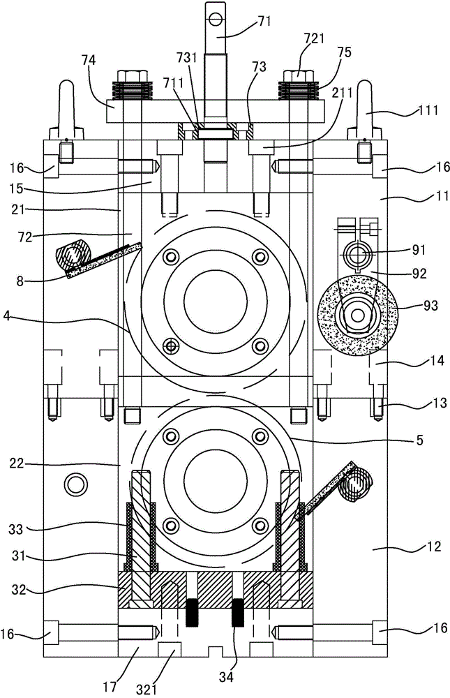
[0024] Such as Figure 3 to Figure 6, the embodiment of the present invention discloses a rotary die-cutting device, which includes a knife holder, two upper bearing seats 21 and two lower bearing seats 22, and the knife holder includes two upper inverted U-shaped frames 11 arranged at intervals and two lower bearing seats arranged at intervals. U-shaped frames 12, each of the inverted U-shaped frames 11 is respectively arranged on the top of each lower U-shaped frame 12, and the two are connected by bolt locking. 12. The specific connection method is: four threaded holes 13 are correspondingly provided around the upper surface of the U-shaped pins of each lower U-shaped frame 12, and four threaded holes 13 are respectively arranged around the upper surface of the U-shaped pins of each upper inverted U-shaped frame 11. The positions correspond...


PUM


Abstract

The invention provides a rotation die cutting device capable of preventing the axial back-and-forth movement of a cutter die roll and a bottom roll in a high-speed rotation process, and prolonging the service life. The rotation die cutting device comprises a tool rest, a cutter die roll and a bottom roll, wherein the upper and lower positions of the middles of two sides of the tool rest are respectively and detachably provided with two upper bearing bases and two lower bearing bases; the part, positioned between the upper bearing bases and the lower bearing bases, of the tool rest is provided with a pressure regulating device, and the cutter die roll is rotatably arranged between the two bearing bases by virtue of bearings; the bottom roll is rotatably arranged between the two bearing bases by virtue of bearings, two ends of the cutter die roll and two ends of the bottom roll are respectively and coaxially connected with a shaft neck, and each bearing is respectively arranged on each shaft neck; each bearing base is connected with the tool rest in a locking manner, and a guide positioning device is arranged between each lower bearing base and the tool rest; the parts, which are positioned in the inner sides of the bearings, of the shaft necks are respectively provided with a limiting step A used for preventing each bearing from shifting towards the middle of the tool rest; the part, positioned on the outer side of each bearing, of each shaft neck is provided with an axial clearance displacement prevention device used for preventing each bearing from displacing towards two sides of the tool rest.

Description

technical field [0001] The invention relates to product cutting equipment, in particular to a rotary die cutting device. Background technique [0002] In the production process of sanitary napkins and diapers, it is often necessary to use a rotary die-cutting device to die-cut their shapes, such as figure 1 and figure 2 , the existing rotary die-cutting device includes a frame body 1', a rotatable cutter die roller 2' and a bottom roller 3' arranged on the frame body 1', and a cutter die roller 2' and a bottom roller 3' respectively installed on the frame body 1'. 'The upper bearing sleeve 8' and the lower bearing sleeve 9' at both ends and the upper slider 14' and the lower slider 15' connected with the upper bearing sleeve 8' and the lower bearing sleeve 9' respectively, the frame 1' is located on the upper A pressurizing mechanism is provided above the slider 14', and the pressurizing mechanism cooperates with the upper bearing sleeve 8' through the upper slider 14', a...

Claims


Application Information

Patent Timeline
IPC IPC(8): B26D7/26
Inventor 蔡金泽
Owner 晋江特锐模具有限公司
Why Eureka
Try Eureka