Positioning device for wood board drilling

A technology of positioning device and plank, which is applied in the direction of drilling machines, wood processing equipment, manufacturing tools, etc., can solve the problem of lack of fixing devices, etc., and achieve the effect of clamping stability

Inactive Publication Date: 2015-04-29
CHONGQING MINGMU FURNITURE
0 Cites 3 Cited by

AI-Extracted Technical Summary

Problems solved by technology

During the processing of furniture, it is often necessary to drill the fur...

Abstract

The invention discloses a positioning device for wood board drilling, which is used for positioning while drilling a wood board. The positioning device comprises a clamp body, wherein intersected horizontal hole and vertical hole are formed in the clamp body; a drive rod is connected in the vertical hole in a sliding manner; a boosting cylinder is connected to a drive end of the drive rod; a driven end of the drive rod is positioned at the juncture part of the horizontal hole and the vertical hole; an inclined plane is arranged at the driven end; a tension rod is axially connected in the horizontal hole in the sliding manner; idler wheels which are matched with the inclined plane on the drive rod are arranged on the tension rod; the bottom part of the tension rod is connected with the clamp body through a spring; and threaded holes are formed in the head of the tension rod and are in threaded connection with clamping jaws. The boosting cylinder can generate relatively strong drive force, so that clamping is relatively stable; and the contact between the idler wheels and the inclined plane is relatively tight due to the spring.

Application Domain

Drilling machines

Technology Topic

EngineeringWood panel +1

Image

  • Positioning device for wood board drilling

Examples

  • Experimental program(1)

Example Embodiment

[0011] The present invention will be further described in detail below through specific embodiments:
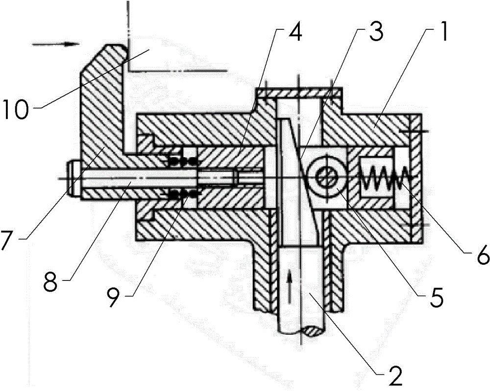
[0012] The reference signs in the drawings of the specification include: clamping body 1, driving rod 2, inclined surface 3, tension rod 4, roller 5, spring 6, clamping jaw 7, bolt 8, compression spring 9, and workpiece 10.
[0013] The embodiment is basically as attached figure 1 Shown: the clamp body is fixed under the workpiece, the inside of the clamp body is provided with intersecting horizontal and vertical holes, and its tail end is sealed by a plate. The vertical hole is slidingly connected with a drive rod, and the drive end of the drive rod is connected with In the double-force cylinder shown in the figure, the piston rod of the double-force cylinder extends vertically upward and is connected to the lower end of the drive rod through a coupling.
[0014] The upper end of the driving rod is provided with an inclined surface, and is located at the intersection of the horizontal hole and the vertical hole. A tension rod is slidably connected to the horizontal hole in the axial direction. It is connected by a bearing, and the bottom of the tension rod is connected to the right of the clamp body by a spring. When the double-force cylinder drives the driving rod to move, the inclined surface on the driving rod pushes the roller, so that the tension rod moves axially under the action of the horizontal component force.
[0015] The head end of the tension rod is provided with a threaded hole and is screwed with a clamping jaw. The clamping jaw is L-shaped, and its two sides are perpendicular to each other. The horizontal side is provided with a through hole. The bolt passes through the through hole to connect the clamping jaw to the tension rod. A compression spring is also arranged between the clamping jaw and the tension rod.
[0016] After the tension rod is moved, the clamping jaw can be driven to compress the left side of the workpiece, and the initial distance can be adjusted by the thread between the clamping jaw and the tension rod to adapt to different workpiece processing.
[0017] The above are only the embodiments of the present invention, and common knowledge such as specific structures and characteristics that are well-known in the solutions are not described here. It should be pointed out that for those skilled in the art, without departing from the structure of the present invention, several modifications and improvements can be made. These should also be regarded as the protection scope of the present invention, and these will not affect the implementation of the present invention. Effectiveness and utility of patents. The scope of protection claimed in this application shall be subject to the content of the claims, and the specific implementation modes in the description can be used to interpret the content of the claims.

PUM

no PUM

Description & Claims & Application Information

We can also present the details of the Description, Claims and Application information to help users get a comprehensive understanding of the technical details of the patent, such as background art, summary of invention, brief description of drawings, description of embodiments, and other original content. On the other hand, users can also determine the specific scope of protection of the technology through the list of claims; as well as understand the changes in the life cycle of the technology with the presentation of the patent timeline. Login to view more.

Similar technology patents

Novel mounting device of municipal road indication board

InactiveCN107180588AStable clampingEasy to remove and replace
Owner:朱辉

Sensor with protection mechanism

PendingCN114543860AStable clampingEasy to fix the position of the sensor body
Owner:朱英

10kV high-voltage fuse dismounting and mounting tool

Owner:GUANGDONG POWER GRID CO LTD DONGGUAN POWER SUPPLY BUREAU

Electric power safety object connection ground wire clamping device

InactiveCN112490705AAdjustable clamping rangeStable clamping
Owner:郭连坤

Classification and recommendation of technical efficacy words

  • Stable clamping

Rotary mechanical fixture matched with robot

ActiveCN107813332AEasy control and dockingStable clamping
Owner:SUZHOU HAGONG ZHONGZHI AUTOMATIC TECH CO LTD

Device capable of stably clamping safety valve

ActiveCN106425485AStable clamping
Owner:SPECIAL EQUIP SAFETY SUPERVISION INSPECTION INST OF JIANGSU PROVINCE +1

Self-locking hydraulic cylinder

ActiveCN108999832AStable clampingovercoming retraction
Owner:CHONGQING WEIQING HYDRAULIC MACHINERY CO LTD

Insert-block vise jaw

InactiveCN103056790AProtection against displacement or damageStable clamping
Owner:张景丰
Why Eureka
Try Eureka