Cyclone electric dehydration device with driving impeller

An electric dehydration and swirling technology, which is applied in the fields of electric/magnetic dehydration/demulsification, mechanical dehydration/demulsification, and petroleum industry, etc. Dehydration time and other issues, to achieve the effect of shortening dehydration treatment time, improving dehydration efficiency, and wide application range

Inactive Publication Date: 2016-04-20
承德石油高等专科学校
View PDF10 Cites 2 Cited by
  • Summary
  • Abstract
  • Description
  • Claims
  • Application Information

AI Technical Summary

Problems solved by technology

[0005] In order to overcome the shortcomings of the existing crude oil electric dehydration device, such as large volume, long dehydration time, low dehydration efficiency of high-viscosity crude oil, and the need for regular sand cleaning, the present invention provides a swirling electric dehydration device with a driving impeller. The electric dehydration device can Effectively improve the dehydration efficiency of crude oil, reduce the volume of the dehydration device, shorten the dehydration time, no need to remove sand, and have a good dehydration effect on high-viscosity crude oil and difficult-to-dehydrate crude oil

Method used


Image

  • Cyclone electric dehydration device with driving impeller
  • Cyclone electric dehydration device with driving impeller

Examples


Embodiment Construction

[0022] In order to better understand the present invention, the present invention will be further described below in conjunction with specific examples and accompanying drawings.

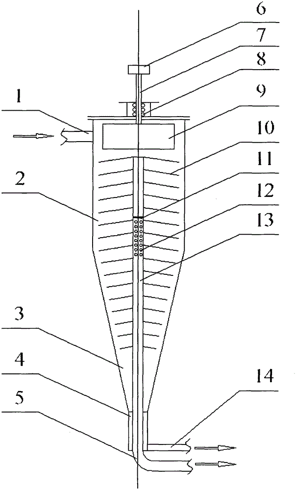
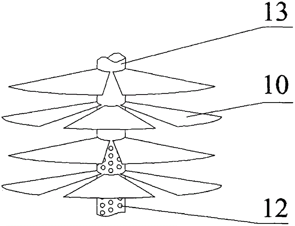
[0023] Such as figure 1 and figure 2 As shown, a swirling electric dehydration device with a driving impeller includes an oil inlet pipe 1, an upper straight section 2, a cone section 3, a lower straight section 4, an oil outlet pipe 5, a transmission wheel 6, a transmission shaft 7, a seal Ring 8, driving impeller 9, electrode plate 10, separator 11, oil collecting hole 12, oil collecting pipe 13 and drain pipe 14;

[0024] The upper straight section 2, the cone section 3 and the lower straight section 4 are sequentially connected coaxially from top to bottom to form a hydrocyclone; the oil inlet pipe 1 is on the upper part of the upper straight section 2 It communicates with the upper straight section 2 and is tangent to it; the drain pipe 14 communicates with the lower straight section 4 at th...


PUM


Abstract

The invention discloses a spiral-flow type electric dehydrating device with a driving impeller; a hydrocyclone is composed of an upper straight tube section, a conical tube section and a lower straight tube section, wherein an oil inlet tube is communicated with the upper straight tube section in a tangential direction and a drainage pipe is communicated with the lower straight tube section in a tangential direction; the driving impeller is arranged on the upper side of the upper straight tube section; the driving impeller is connected to a driving wheel by virtue of a transmission shaft; an oil collecting pipe is arranged in the axis position of the hydrocyclone; the oil collecting pipe is a hollow pipe; the top end of the oil collecting pipe is sealed; a plurality of oil collecting holes are formed in the middle of the oil collecting pipe; a partition board is arranged on the upper sides of the oil collecting holes to divide the oil collecting pipe into two sections; the lower end of the oil collecting pipe extends out of the lower straight tube section from the lower end of the lower straight tube section of the hydrocyclone; multiple layers of umbrella-shaped electrode plates are arranged around the oil collecting pipe, and the multiple layers of the electrode plates are installed in a staggered manner; the various layers of the electrode plates on the upper surface are powered by high-voltage alternating current, and the various layers of the electrode plates on the lower surface are powered by high-voltage direct current.

Description

Technical field [0001] The invention relates to a method for dehydrating crude oil emulsion in a mine, in particular to a crude oil dehydrating device with a driving impeller and a cyclone. Background technique [0002] The crude oil extracted from the oil field contains more water, so it needs to be dehydrated. Free water in crude oil can be separated from crude oil by simple sedimentation method; while emulsified water in it forms water-in-oil emulsion with oil, which is difficult to remove, and special dehydration measures must be adopted. The dehydration of crude oil emulsion usually adopts electric dehydration device. [0003] At present, the crude oil electric dehydration device consists of a tank body and electrode plates suspended inside the tank body. The water droplets in the crude oil emulsion collide with each other in the high-voltage electric field generated by the electrode plate, coalesce into larger water droplets, and then settle and separate from the cru...

Claims


Application Information

Patent Timeline
Patent Type & Authority Patents(China)
IPC IPC(8): C10G33/02C10G33/06
CPCC10G33/02C10G33/06C10G2300/201
Inventor 徐进
Owner 承德石油高等专科学校
Why Eureka
Try Eureka