Sealing connecting structure of casing of gas well

A connection structure and casing technology, which is applied in the direction of casing, drill pipe, drilling equipment, etc., can solve the problems of easy damage in hoisting and stabbing, small guide surface inclination, low processing efficiency, etc., to achieve easy stabbing, reduce Effect of stress concentration and high processing efficiency

Active Publication Date: 2015-04-29
DALIPAL PIPE
View PDF11 Cites 4 Cited by
  • Summary
  • Abstract
  • Description
  • Claims
  • Application Information

AI Technical Summary

Problems solved by technology

[0004] 1) Although the partial ladder thread is used, the inclination angle of the guide surface is small, the length is short, it is not easy to buckle and the buckle is easy to stick;
[0005] 2) The thread bearing surface is inclined downward, which leads to low processing efficiency and high cost;
[0006] 3) The bearing surface of the thread is in contact with the guide surface, and the top and bottom of the tooth are parallel to the axis of the pipe body, making it difficult to detect;
[0007] 4) The sealing position is close to the shoulder (3~4mm apart), which is prone to damage during hoisting and stapling

Method used


Image

  • Sealing connecting structure of casing of gas well
  • Sealing connecting structure of casing of gas well
  • Sealing connecting structure of casing of gas well

Examples


Embodiment Construction

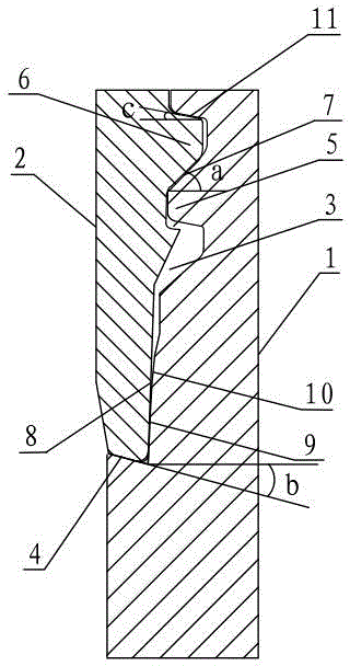
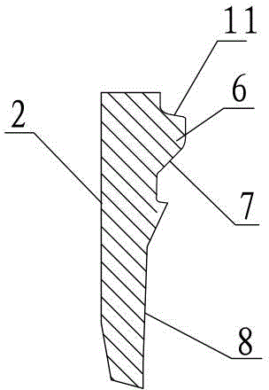
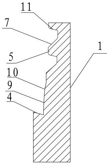
[0022] Such as figure 1 , figure 2 and image 3 Shown: a gas well casing sealing connection structure, including a male pipe head 1 and a female pipe head 2, the male pipe head 1 is inserted into the female pipe head 2, and the contact between the male pipe head 1 and the female pipe head On the surface are the threaded connection part, the oil storage relief groove 3, the sealing surface and the torque shoulder 4 in sequence. The thread 6, the external thread 5 and the internal thread 6 are partial trapezoidal threads, the inclination angle a of the guide surface 7 contacted between the external thread 5 and the internal thread 6 is 25 ° ~ 45 °, the internal thread The tooth height of 6 is 1.45~1.65mm, and the tooth height of external thread 5 is 1.65~1.85mm; the sealing surface is composed of the first tapered surface 8 on the inner wall of the female pipe head 2 and the spherical surface 10 and the outer wall of the male pipe head 1 respectively. The second conical surf...


PUM


Abstract

The invention discloses a sealing connecting structure of a casing of a gas well, and relates to the technical field of equipment for oil and gas wells. The sealing connecting structure comprises a male pipe connector and a female pipe connector. A threaded connecting portion, a sealing surface and a torque shoulder are sequentially arranged on contact surfaces of the male pipe connector and the female pipe connector, an oil storage tool withdrawal groove is formed in the contact surfaces of the male pipe connector and the female pipe connector, angles a of contact guide surfaces between external threads and internal threads range from 25 degrees to 45 degrees, a first conical surface on the inner wall of the female pipe connector, a spherical surface on the outer wall of the male pipe connector and a second conical surface on the outer wall of the male pipe connector are squeezed by one another and are in contact with one another so as to form the sealing surface, the conicity of the first conical surface ranges from 1 / 12 to 1 / 16, the conicity of the second conical surface ranges from 1 / 6 to 1 / 8, and the oil storage tool withdrawal groove is formed in a position between the threaded connecting portion and the sealing surface; the torque shoulder is arranged on the male pipe connector, an end of the female pipe connector and the torque shoulder are fittingly in contact with each other, and an inclination angle b of the torque shoulder ranges from -6 degrees to -15 degrees. The sealing connecting structure has the advantages that the torque shoulder and the sealing surface are optimally designed, accordingly, shortcomings of existing threaded connectors can be overcome, the sealing connecting structure is easy to screw on in a site and convenient to detect, and reliable sealing effects can be realized.

Description

technical field [0001] The invention relates to the technical field of oil and gas well equipment. Background technique [0002] Oil casing strings are formed by connecting single casings with threaded couplings. The threaded joint connecting two single casings is a key factor affecting the safety and life of the casing string. The connection joints include API standard joints and special threaded joints. [0003] my country's western oilfields, Daqing, Tarim and other gas fields all have the characteristics of high temperature (150°C) and high pressure (above 55MPa), requiring threaded joints with high reliable sealing characteristics for casings under continuous cyclic loads, which cannot be met by ordinary API threaded joints. It requires that special threaded joints must be used to meet its sealing performance requirements. However, most of the special threaded joints on the market, such as VAM buckle, 3SB buckle, NSCC buckle, SEC buckle, VAGT buckle, TPCQ buckle, BGC bu...

Claims


Application Information

Patent Timeline
Patent Type & Authority Applications(China)
IPC IPC(8): E21B17/08
CPCE21B17/08
Inventor 李玲霞穆增利邓叙燕殷志祥
Owner DALIPAL PIPE
Why Eureka
Try Eureka