A diffuser structure applied to compressor

A compressor and diffuser technology, which is applied in the field of compressor accessories, can solve the problems of surge, flow deterioration of the flow channel, and rotation separation, etc., and achieves the effects of low production cost, improved gas flow, and increased gas flow rate.

Active Publication Date: 2018-09-07
GREE ELECTRIC APPLIANCES INC +1
View PDF7 Cites 0 Cited by
  • Summary
  • Abstract
  • Description
  • Claims
  • Application Information

AI Technical Summary

Problems solved by technology

[0006] The purpose of the present invention is to propose a diffuser structure applied to compressors to solve the serious deterioration of the flow rate in the flow channel of the compressor under the condition of light load in the prior art, the phenomenon of rotation separation and "surge" The problem of phenomena

Method used


Image

  • A diffuser structure applied to compressor
  • A diffuser structure applied to compressor
  • A diffuser structure applied to compressor

Examples


Embodiment 1

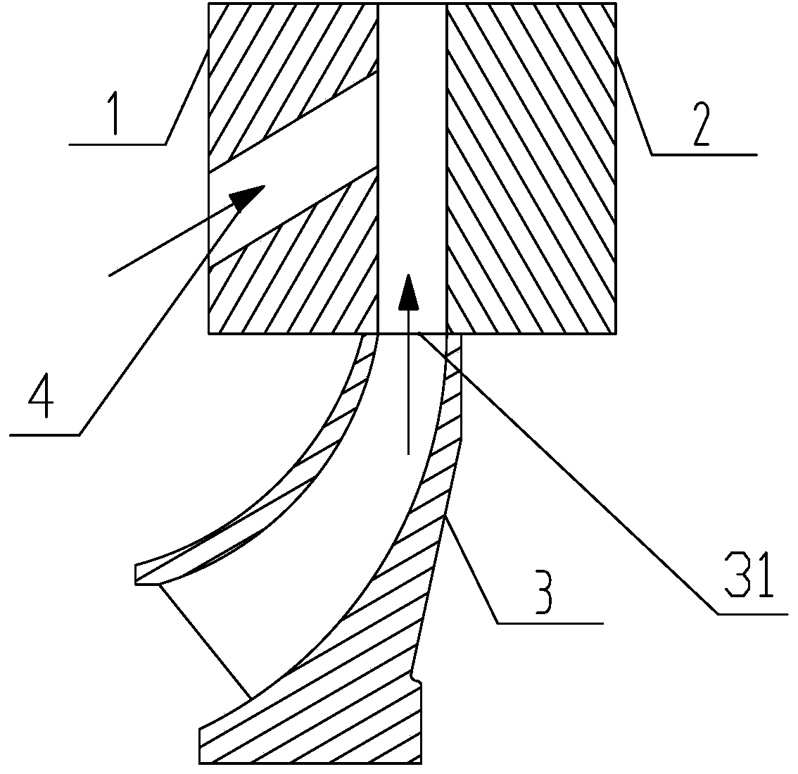
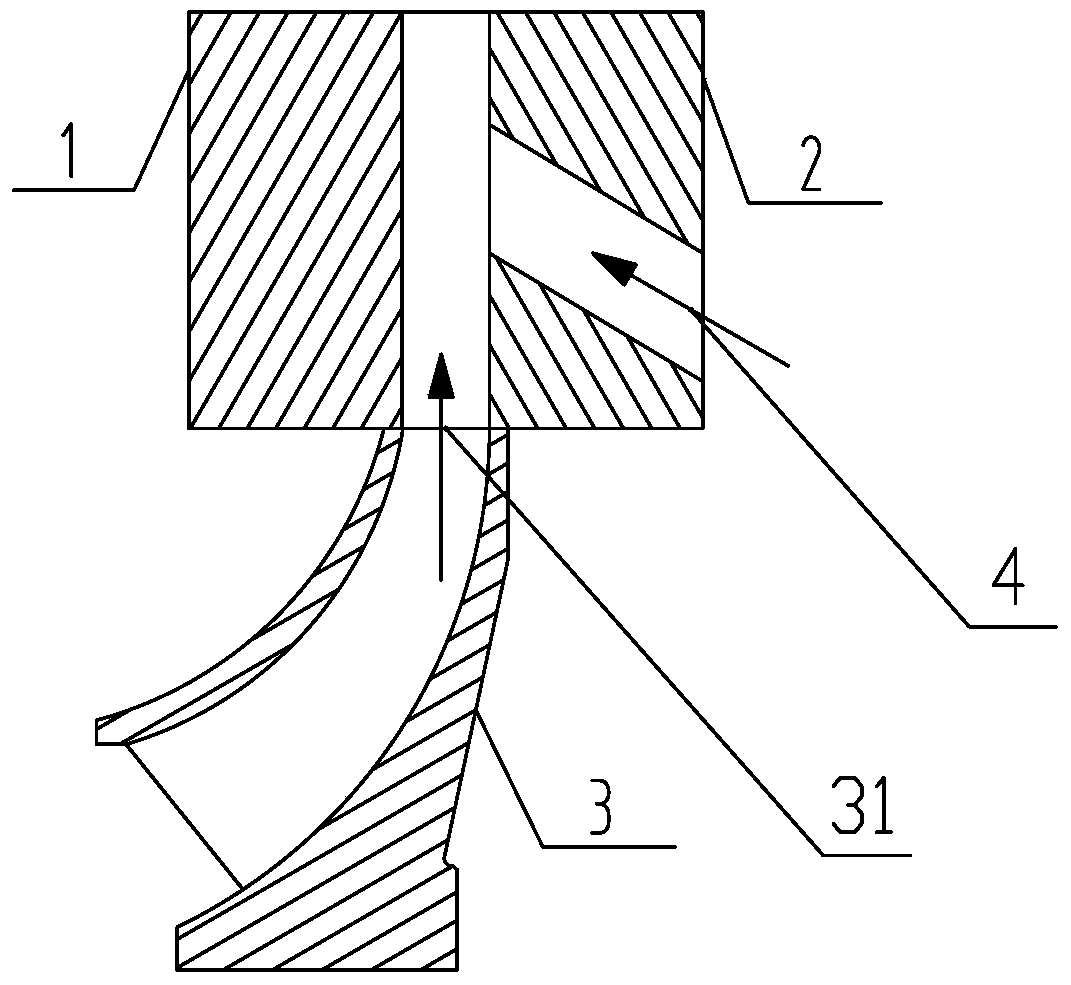
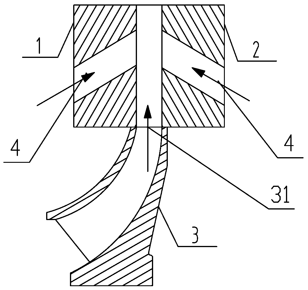
[0043] Such as Figure 4 , Figure 5As shown, it is a specific embodiment of a diffuser structure applied to a compressor proposed in this embodiment. In this embodiment, a high-pressure gas channel 4 is set on the first wall surface 1, and the high-pressure gas channel 4 is a circular channel. Holes, the axis of the circular through-hole high-pressure gas channel 4 and the side wall of the first wall 1 are set at an angle of β, and the value of β is 40°-90°, which is 60° in this embodiment.

[0044] The included angle between the projection of the axis of the high-pressure gas channel 4 on the first wall 1 and the axis line is α, and the included angle α is consistent with the outlet angle of the equipment that delivers high-pressure refrigerant to the high-pressure gas channel 4. In this implementation In the example, the included angle α is an acute angle of 60°.

[0045] The high-pressure gas channel 4 processed according to the above requirements also has the effect of ...

Embodiment 2

[0049] Such as Image 6 with Figure 7 Shown is a specific implementation of a diffuser structure applied to a compressor proposed in this embodiment.

[0050] The shape of the high-pressure gas channel 4 in this embodiment is a fan-shaped annular through hole, the axial direction of the fan-shaped ring-shaped through hole is perpendicular to the side wall of the first wall 1, and the high-pressure refrigerant enters the gas outlet channel along the direction perpendicular to the first wall 1 among. For the fan-shaped through hole, the high-pressure refrigerant will be distributed around the first wall 1 along the fan-shaped hole, further increasing its range of action.

[0051] The number of high-pressure gas passages 4 in the fan-shaped through-holes in this embodiment is four, which are evenly arranged on the first wall surface 1 along the circumferential direction. Of course, it can also be arranged on the second wall surface 2 , or be arranged on the first wall surface...

Embodiment 3

[0053] Such as Figure 8 with Figure 9 Shown is a specific implementation of a diffuser structure applied to a compressor proposed in this embodiment.

[0054] In this embodiment, a high-pressure gas channel 4 with an annular groove structure is provided on the first wall 1 or the second wall 2, and the annular groove structure in this embodiment is adopted so that the high-pressure refrigerant enters the gas outlet channel along a direction perpendicular to the first wall 1 among.

[0055] The high-pressure gas channel 4 of the annular groove structure is conducive to further increasing the range of action of the annular "gas-sealed wall". For the high-pressure gas channel 4 of the annular groove structure, the introduced high-pressure refrigerant will form a continuous and uninterrupted "air-tight wall" zone near the wall surface where the annular groove is set, and its effect is compared with that of the first and second embodiments. The structural effect is better.


PUM


Abstract

The invention relates to the technical field of compressor accessories, and discloses a diffuser structure applied to a compressor. The diffuser structure comprises a first wall face and a second wall face, and the first wall face and the second wall face are fixed on a compressor shell and are opposite to each other. A gas outlet channel communicated with an impeller gas outlet is formed between the first wall face and the second wall face. The first wall face and / or the second wall face are provided with high-pressure gas channels used for injection of high-pressure refrigerants. The diffuser structure has the advantages that the first wall face and the second wall face are provided with the high-pressure gas channels, the high-pressure refrigerants are injected into the high-pressure gas channels and enter the gas outlet channel through the high-pressure gas channels, and a 'gas seal wall' structure is formed on one side wall of each of the first wall face and the second wall face; by the 'gas seal wall' structures, the area of a position, allowing gas to pass, in the gas outlet channel can be reduced effectively, gas flow rate of the position can be increased, and gas backflow can be prevented.

Description

technical field [0001] The invention relates to the technical field of compressor accessories, and more specifically discloses a diffuser structure applied to a compressor. Background technique [0002] In the channel of the centrifugal compressor, due to the reduction of the load required by the customer, when the flow rate is significantly reduced, the flow rate of the air flow in the channel will be seriously deteriorated, and then the phenomenon of rotation and separation will appear. When the gas flow forms a sudden stall during the flow process, the flow state inside the centrifugal compressor will be severely deteriorated and cause gas backflow. This periodic gas backflow will cause the centrifugal compressor system to undergo a phenomenon of circumferential low-frequency large-scale oscillation, that is, "surge". [0003] In order to avoid the "surge" phenomenon in the process of compressor movement, the existing centrifugal compressor mainly uses the device of adju...

Claims


Application Information

Patent Timeline
Patent Type & Authority Patents(China)
IPC IPC(8): F04D29/44F04D29/66
CPCF04D29/462F04D29/661
Inventor 张竞邹颖男钟瑞兴张治平王修川石建钢蒋楠刘明全蒋彩云谢蓉陈玉辉刘建飞周义黄保乾
Owner GREE ELECTRIC APPLIANCES INC
Why Eureka
Try Eureka