Pneumatic valve control mechanism

A control mechanism and pneumatic valve technology, applied to engine components, valve details, valve devices, etc., can solve the problems of directly operating valves, such as laborious use, inability to operate remotely, and affecting convenience

Inactive Publication Date: 2015-04-29
JIANGSU MARITIME INST
View PDF9 Cites 7 Cited by
  • Summary
  • Abstract
  • Description
  • Claims
  • Application Information

AI Technical Summary

Problems solved by technology

[0002] In fluid conveying pipelines, valves are widely used, but at present, valves can only be switched on and off by directly operating the valve stem, and cannot be operated remotely; and for some precision instruments, it is required to accurately control the v...

Method used


Image

  • Pneumatic valve control mechanism
  • Pneumatic valve control mechanism

Examples


Embodiment Construction

[0014] The present invention will be described in further detail below in conjunction with the accompanying drawings.

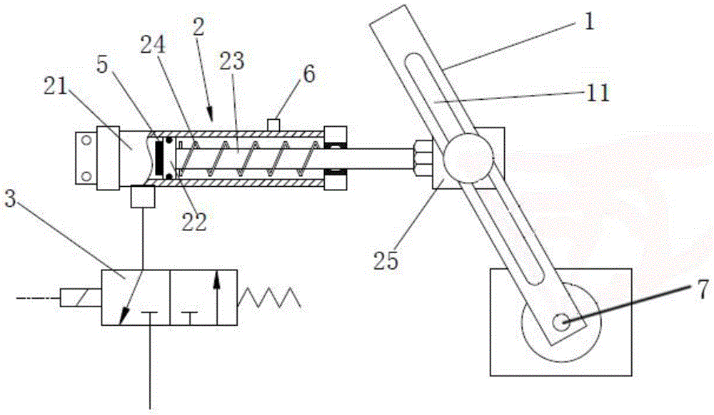
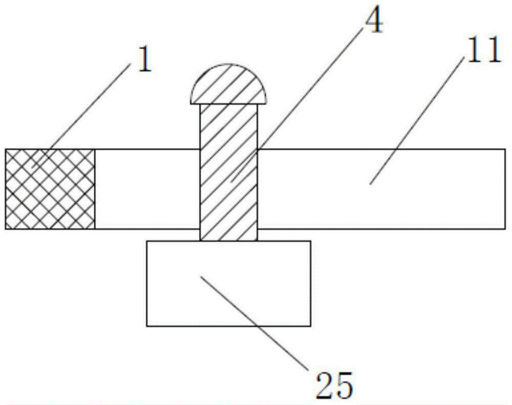
[0015] A pneumatic valve control mechanism, comprising a guide arm 1, a driving cylinder 2, and a two-position three-way electromagnetic reversing valve 3; the inlet of the electromagnetic reversing valve is connected to compressed air, and the air outlet is connected to the inlet of the driving cylinder 2; the guide arm 1. One end is connected with the drive shaft 7 of the valve spool; the guide arm 1 is provided with a long through-hole chute 11; the driving cylinder 2 includes a cylinder body 21, a piston 22, a piston rod 23, a spring 24 and a guide block 25; 23 is arranged in the rodless cavity of the drive cylinder 2; the guide block 25 is arranged on the top of the piston rod 23; the guide block 25 is fixedly connected with the slide shaft 4 which is vertically arranged with the piston rod 23; the slide shaft 4 is slidably installed in the chute 11 ;

...


PUM


Abstract

A pneumatic valve control mechanism is characterized by comprising a guide arm, a drive air cylinder and a magnetic reversing valve. An air inlet of the magnetic reversing valve is used for compressed air to be fed, and an air outlet is connected with an air inlet of the drive air cylinder. One end of the guide arm is connected with a valve element drive shaft of the valve, the guide arm can rotate around the valve element drive shaft of the valve and is provided with a chute, a slide shaft is installed in the chute, and the slide shaft is connected with a piston rod of the drive air cylinder to jointly form a connecting rod mechanism. The reciprocating motion of the piston rod drives the slide shaft to slide in the chute of the guide arm so as to form the connecting rod motion mechanism, the guide arm is driven to perform reciprocating rotation around the valve element drive shaft of the valve and further open or close the valve, and remote control of the valve is achieved through the magnetic reversing valve. On the basis, the position required to be reached, of the piston rod can be calculated according to the opening degree of the valve, then the position of a proximity switch sensing end on the drive air cylinder is adjusted, and accordingly accurate positioning during valve opening is achieved.

Description

technical field [0001] The invention relates to a valve control device, in particular to a pneumatic valve control mechanism. Background technique [0002] In fluid conveying pipelines, valves are widely used, but at present, valves can only be switched on and off by direct operation of the valve stem, and cannot be operated remotely; moreover, for some precision instruments, it is required to accurately control the valve opening, and manual operation of the valve is required. The lever is far from enough, so the current technology affects its convenience of use to a certain extent, and it is more laborious to use the direct operation valve, which affects its ease of use. Contents of the invention [0003] The invention provides a pneumatic valve control mechanism with simple structure and convenient use, which can realize opening and closing of the valve by remote operation without directly operating the valve. The specific technical scheme is as follows: [0004] A pne...

Claims


Application Information

Patent Timeline
IPC IPC(8): F16K31/12F16K31/06
CPCF16K31/12F16K31/06
Inventor 梁恩胜孙长飞刘文科惠节徐晓
Owner JIANGSU MARITIME INST
Why Eureka
Try Eureka