Pipeline heat transfer air cooler for powder

An air cooler and powder technology, applied in the direction of heat exchanger types, heat exchanger shells, indirect heat exchangers, etc., can solve the problems of large footprint, heavy equipment, complex structure, etc., and achieve low maintenance costs, The effect of small footprint and low flow speed

Inactive Publication Date: 2016-09-14
CNBM HEFEI POWDER TECH EQUIP CO LTD
View PDF9 Cites 0 Cited by
  • Summary
  • Abstract
  • Description
  • Claims
  • Application Information

AI Technical Summary

Problems solved by technology

In addition to providing strong cooling air, this type of equipment must be equipped with an additional power source to drive the moving parts to perform rotary motion or reciprocating motion. The structure is complex, the equipment is heavy, the floor area is large, the investment is high, and the efficiency is low.

Method used


Image

  • Pipeline heat transfer air cooler for powder
  • Pipeline heat transfer air cooler for powder
  • Pipeline heat transfer air cooler for powder

Examples


Embodiment 1

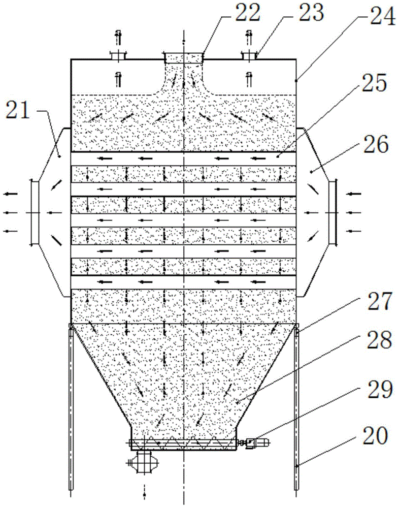
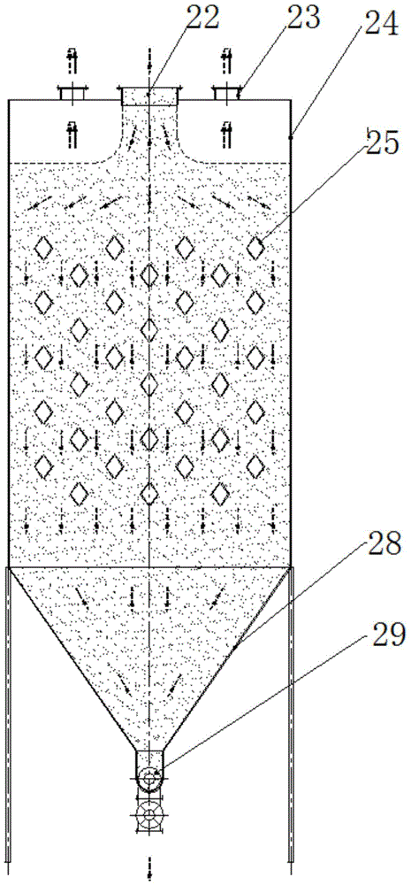
[0038] The pipe heat transfer air cooling zone for powder includes a box-shaped outer casing 24 , and a feeding port 22 is arranged on the top of the outer casing 24 for feeding high-temperature powdery materials into the outer casing 24 . A discharge port 28 is provided on the bottom of the outer shell 24 or on the side close to the bottom, for discharging the cooled powdery material. The discharge port 28 forms a cooling chamber together with the outer casing 24 . The bottom of the outer casing 4 is provided with a weighing sensor 27 for detecting the amount of powdery material stored inside the outer casing 24 . The discharge port 28 is provided with a powder conveying device 29 , and the powder conveying device 29 quantitatively sends the cooled powdery material away from the cooler according to the amount of the powdery material stored in the outer casing 24 . In this structure, the powdery material only runs downwards in the cooling chamber, not upwards.

[0039] The i...

Embodiment 2

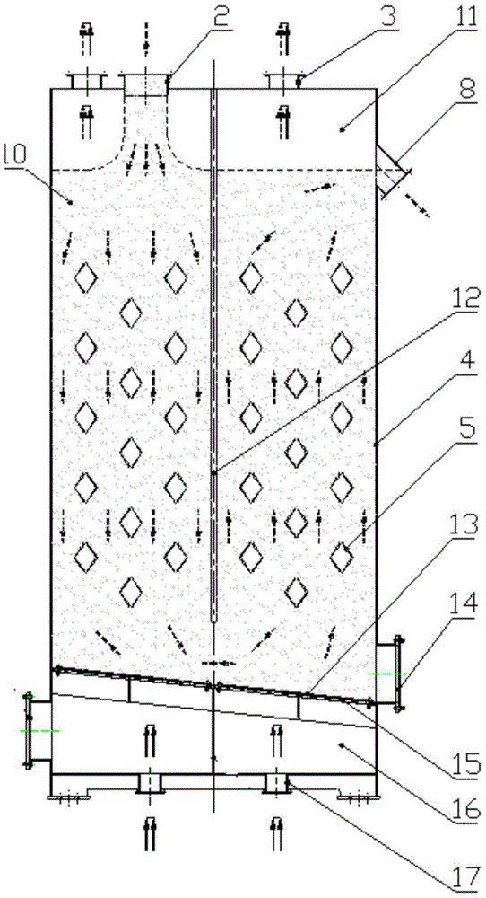
[0043] The air-cooling zone for powder with pipeline heat transfer includes a box-shaped outer casing 4 , and a feed inlet 2 is arranged on the top of the outer casing 4 for feeding high-temperature powdery materials into the outer casing 4 . The upper side of the outer shell 4 is provided with a discharge port 8 for discharging the cooled powdery material. The bottom area of ​​the outer casing 4 is obliquely provided with an air-permeable layer 13, the air-permeable layer on the side of the feed port 2 is slightly higher than the air-permeable layer on the side of the discharge port 8, and the air-permeable layer 13 will cover the outer shell 4. It is divided into an upper cooling chamber and a lower plenum chamber 16 . The outer casing of the lower plenum chamber 16 is provided with an air inlet 17 for feeding air of a certain pressure, and the air of a certain pressure passes through the air-permeable layer 13 under the action of its own pressure, and in the air-permeable l...


PUM


Abstract

The invention discloses a pipeline heat transfer type air cooler for powder. The pipeline heat transfer type air cooler for powder comprises a box type outer shell and is characterized in that a feed hole and a discharge hole are formed in the outer shell, the discharge hole is provided with powder conveying equipment, a plurality of vent pipelines are arranged in the outer shell, and two ends of each vent pipeline pass through the outer shell and are communicated with the outside of the shell. By means of the pipeline heat transfer type air cooler for powder, the flow speed of powder-shaped material in the cooler is low, and the abrasion is small. Cooling medium is air, and accordingly the abrasion is avoided. The cooling medium is clean air before and after cooling, the cooling medium can be discharged directly, and the cooling medium is unlimited. The secondary resource and secondary energy consumption is less, the floor space is less, the investment is less, the energy consumption is low, the reliability is high, and the maintenance cost is low.

Description

technical field [0001] The invention relates to powder cooling technology, in particular to a pipeline heat transfer air cooler for powder. Background technique [0002] In the prior art, the cooling of powdery materials is mainly vertical spiral cooler, chute cooler, composite cooler, etc., and the cooling of bulk materials is mainly single-tube cooler, multi-tube cooler, grate cooler, etc. cooler etc. [0003] Please refer to "1.1 Vertical Spiral Cooler" in the paper "Energy Efficiency Analysis and Comparison of Several Cement Cooling Methods" in the journal "Sichuan Cement" with the classification number of CLC: TQ172.622.4, No. 4, 2008, page 8 "And "1.2 chute cooler", etc. [0004] You can also refer to the invention patent "air cooler" with the application number CN201310122101 and the publication (announcement) number CN103225959A, and the invention patent "composite cooling powder cooler" with the application number CN201320670900 and the publication (announcement) ...

Claims


Application Information

Patent Timeline
Patent Type & Authority Patents(China)
IPC IPC(8): F28D7/00F28F9/00F28F27/00
Inventor 王学敏王虔虔何正凯郭宏武
Owner CNBM HEFEI POWDER TECH EQUIP CO LTD
Why Eureka
Try Eureka