Rotary encoder based on light sensation principle and measuring method thereof

A rotary encoder and principle technology, applied in the field of encoders, can solve the problems of complex code disc manufacturing process, inability to meet ultra-high resolution processing and production, etc., and achieve the effect of high physical resolution

Inactive Publication Date: 2015-04-29
FOSHAN QINGZI PRECISION MEASUREMENT & CONTROL TECH
View PDF4 Cites 3 Cited by
  • Summary
  • Abstract
  • Description
  • Claims
  • Application Information

AI Technical Summary

Problems solved by technology

Although this kind of encoder is simple in principle, reliable in operation and strong in anti-interference, the manufacturing process of the code disc is complicated, and the maximum number of code tracks and lines that can be engraved is also limited to a certain extent, which cannot meet the needs of ultra-high resolution processing and production. requirements

Method used


Image

  • Rotary encoder based on light sensation principle and measuring method thereof
  • Rotary encoder based on light sensation principle and measuring method thereof
  • Rotary encoder based on light sensation principle and measuring method thereof

Examples


Embodiment 1

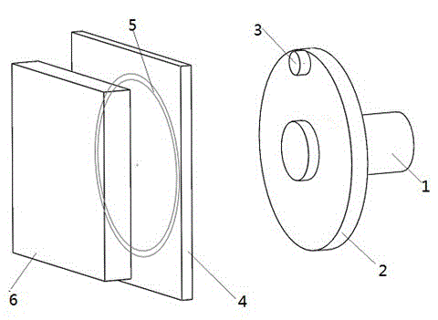
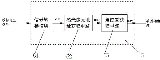
[0029] like figure 1 As shown, it is a schematic structural diagram of a rotary encoder based on the light-sensing principle in this embodiment, including a main shaft 1, which is connected to the measured shaft through a coupling, and a circular wheel 2 is fixed on the main shaft 1, and the laser The emitting device 3 is installed on the circular wheel 2, and the photosensitive resistance surface 4 is located in front of the laser emitting device 3, so that when the main shaft 1 rotates, the laser emitted by the laser emitting device 3 can be formed on the photosensitive resistance surface array. A circular spot track 5, the photosensitive element receiving the spot on the photosensitive photoresistor surface 4 converts the laser signal into an analog voltage signal and transmits it to the signal processing system 6, such as figure 2 As shown, the signal processing system 6 includes a signal conversion module 61, a photosensitive pixel address acquisition circuit 62 and an a...

Embodiment 2

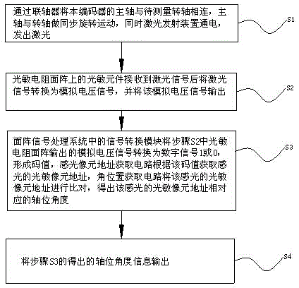
[0031] This embodiment is the measurement method of the rotary encoder based on the light-sensing principle of the present invention, such as image 3 As shown, it specifically includes the following steps:

[0032] S1. Connect the main shaft of the encoder to the rotating shaft to be measured through a coupling, the main shaft and the rotating shaft perform synchronous rotation, and at the same time the laser emitting device is powered on to emit laser light;

[0033] S2. After receiving the laser signal, the photosensitive element on the photoresistor array converts the laser signal into an analog voltage signal, and outputs the analog voltage signal;

[0034] S3. The signal conversion module in the signal processing system converts the analog voltage signal output by the photosensitive resistor area array in step S2 into a digital signal 1 or 0 to form a code value, and the photosensitive pixel address acquisition circuit obtains the photosensitive photosensitive image ac...

Embodiment 3

[0042] In this embodiment, the rotary encoder in Embodiment 1 and the measurement method in Embodiment 1 will be combined;

[0043] For the convenience of illustration, in this embodiment, the photoresistive element irradiated by laser light on the photoresistor array is composed of 4 cmos photosensitive elements (in fact, there are multiple photosensitive elements), and the analog voltage signal output by the photosensitive element irradiated by laser is passed through The signal conversion mode in the signal processing system is converted into a digital signal 1 or 0, specifically: when the first cmos photosensitive element receives the laser signal, and the remaining 3 cmos photosensitive elements do not receive the laser signal, the photosensitive resistance element outputs The analog voltage signal is converted into a specific code value 0001 by the signal conversion module in the signal processing system, and the photosensitive pixel address acquisition circuit ...


PUM


Abstract

The invention discloses a rotary encoder based on a light sensation principle, and belongs to the field of encoders. The encoder comprises a main shaft, a wheel disc is fixed on the main shaft, a laser emission device is installed on the wheel disc, a photoresistance area array is located in front of the laser emission device, and a signal processing system is connected with the photoresistance area array, and meanwhile the invention further discloses a measuring method of the rotary encoder. According to the rotary encoder based on the light sensation principle and the measuring method of the rotary encoder, the position of a mechanical shaft is measured through the photoresistance area array, the fact that the precision of the encoder is restricted by precision machining technology can be avoided, a coded disc of high resolution is not needed to code, and the physical resolution of the rotary encoder is greatly higher than a mechanical coded disc.

Description

technical field [0001] The invention relates to the field of encoders, in particular to a rotary encoding based on the light-sensing principle and a measuring method thereof. Background technique [0002] In the production of modern manufacturing industry, higher and higher requirements are put forward for the precision of mechanical operation. The encoder is a key device that affects the accuracy of the mechanical operation. It feeds back the shaft position information to the control system during the movement of the mechanical shaft to achieve the purpose of accurately controlling the position and speed of the rotary motion of the shaft. [0003] There are two types of encoders: absolute and relative. The absolute encoder can reflect the position information of the mechanical shaft relative to the predetermined origin, while the relative encoder reflects the position information of the current axis relative to the previous axis. [0004] At present, many absolute encod...

Claims


Application Information

Patent Timeline
Patent Type & Authority Applications(China)
IPC IPC(8): G01B11/26
Inventor 王新力
Owner FOSHAN QINGZI PRECISION MEASUREMENT & CONTROL TECH
Why Eureka
Try Eureka